Drip Irritation | Final Project
Table of content:
1 - Problem Statement2 - Work done before Fab Academy
3 - Decide what I want from the project
4 - Selecting the components and IC
5 - Designing the final project board | attiny1614
6 - Testing all the devices onto the final project board | attin1614
6.1 - oled 6.2 - ultrasonic sensor 6.3 - step response 6.4 - Control Board with LM393 Voltage Comparator 6.5 - esp8266-01 and esp8266-12e
7 - Designing the final project board | esp32
8 - Testing all the devices onto the final project board | esp32
9 - Making the water sensor
9.1 - Wire mesh 9.2 - Rain dro like pad 9.3 - Rain drop like pad | with vibration motor 9.4 - Header pin 9.5 - Screw connector and needle
10 - Programming
11 - Modification in the final project board | esp32
12 - Programming the final project board continues
13 - Making the cases
14 - Assembly
15 - Solution
16 - Bill of material
17 - Final project slide and presentation
For my final project, i decided to continue the project i was working on earlier. The old project had a lot of things to improve and since i
decided to continue working on that project, it was
going to cover a lot of aspect of the fab academy like electronics production, electronics design, embedded programming, networking and
communication, interface and application programming, 3d printing, laser cutting and so on. I'll explain about the final project im detail
Problem Statement
In public places like bus station/railway station, i have observed a lot of times that due to wear and tear, the taps/faucets starts to leak
and due to the ignorance or the lack of communication, lots of water is already wasted before someone repair/replaces the tap,
Also a lot of times, people leave the taps fully or partially open after using it,
So i wanted to make a device that not only indicates when there is running water but also gives you the data about how much water is already
being wasted.
Work done before Fab Academy
In July 2017, i participated in a program called "Startup weekend" where you had to pitch an idea and work on that idea in a group and
there will be judges to select best of the ideas and all of this within 72 hours. My idea didn't get selected, however i decided to work onto
the idea. I had the ieda but no knowledge how to execute it so i shared the idea with my friend, Mithilesh Barasara and he help me with making
custom PCB and programming. I'll explain in brief what work was done on the project at that time,
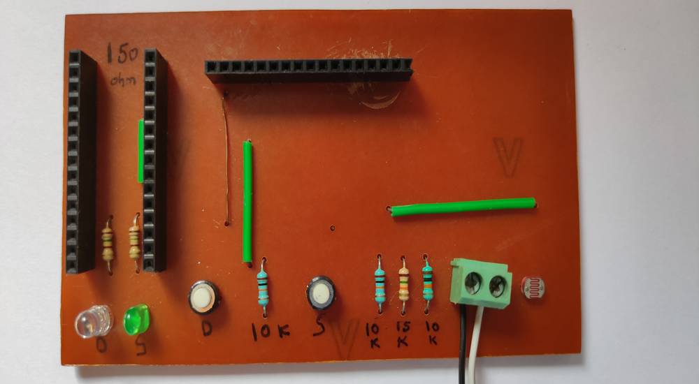
We had to differenciate between usage and leakage of water and for that we used a LDR sensor. Near the washbasin, we need to install a LDR sensor
(receiver) on one end and on the other end install a light(transmitter). When someone is using the tap, they'll be standing in between the LDR sensor
and the light and hence the reading of the LDR sensor will be low and when no one is standing in between the LDR sensor and the light, the light
will fall onto the LDR sensor and
the readings of the LDR sensor will be high. We used these high and low values to detect human presensre.
To detect the running water, we were checking the resistivity/DC conductivity of one of the digital pin with the help of a 10KOhms and 15KOhms
resistors in this arrangement,

So we had to attach something that has two electrodes onto the screw connectors and when the water falls onto that two electrodes, the
resistivity will decrease/conductivity
will increase and vice-a-versa.
We used separate LED's that will turn on after the stream and drop exceeds certain value and separate push button to turn them off.
We used a LCD without I2C module to display the data in the form of stream and drops.
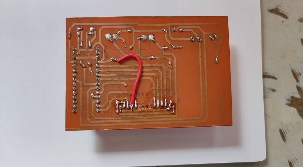
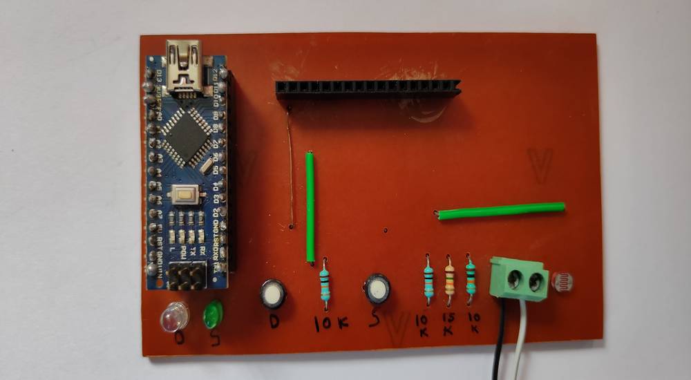
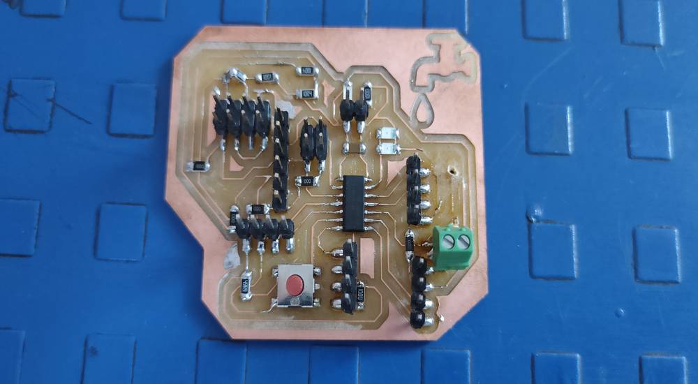
We used a Arduino Nano as the microcontroller. Here is how our PCB looked like,
This is the code we used,
you can copy the code from here too.
Here is a brief explaination about how the code works:
The microcontroller checks the DC conductivity/resistivity every 80/100 miliseconds. Since we were using the digitalRead ,if the
two electrodes get connected with the water the readings of that digital pin will be high and vice-a-versa. When checking if the readings
of that digital pin is high, the microcontroller will start increasing the value of "m".
If the value of "m" is constantly increasing without breaking or we can say that if the state of the digital pins is constantly HIGH then the
microcontroller will increment "+1" in stream after the value of "m" reaches 80. If the value of "m" stops increasing in between or we can say
that if the state of the digital pin is sometimes HIGH and sometimes LOW then the microcontroller will increment "+1" in drop after the
value of "m" reaches 150. Basically the
digital pin 7(input pin of the two resistor) checks every 80-100 miliseconds if there the two electrodes of the screw connectror is connected.
If it is connected, esp32 will start increasing
the value of "m" by +1 every 80-100 miliseconds.
There is line for reset cycle which is set to 90 which only afftects the situation of stream, so after incrementing +1 in the stream the value of
"m" will be 0 again. The new cycle of "m" will again start increasing after the value of reset cycle has reached 90.
The above three situation will occur only if the vlaue of the LDR sensor/photoresistor is above a certain value. Let say when you flash a light
onto the LDR, the value reaches above 200 and when there is no light, the value is around 80. So the value "m" will only increase if the value is
above 200 otherwise only the reset cycle will be in action. Since the value of "m" won't increase, there will be no incrementing in drop
or stream.
When the incremented value of drop and stream reaches a certain number, the microcontroller will turn on the LED dedicated to drop and stream
and we can turn it off without resetting, with the help of two push button dedicated to drop and stream.
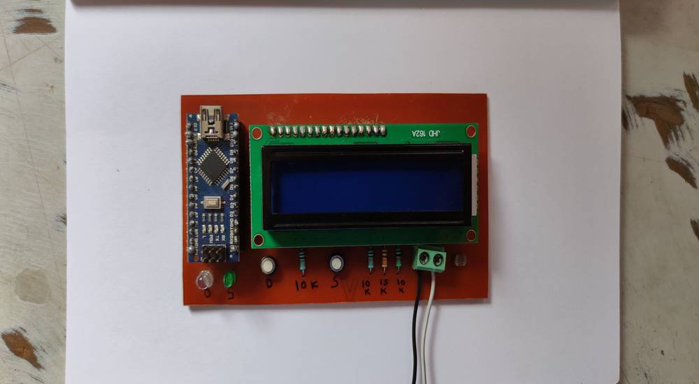
Here is the PCB and the code in action,
For some reason the LCD is not working now and also the LDR is giving strange readings so i temporarily set the value of photoresistor to >10
so that microcontroller will increase the value of "m"
With everything ready and functioning all i had to do was attach two electrodes onto the screw connector that can detect the running water, especially
in the form of drops. I came up with an idea to use two piece of mesh wire and separate them with a thin sheet of MDF and connect
them onto the screw connector. When i tested it, the water either doesn't make any contatct between the two mesh wire or when it does, it gets
stuck between the mesh wire and the contact won't break until given external jerk.
We don't want the water to get stuck between two mesh wire or the microcontroller will keep incrementing +1 in the stream even if there is no
running water. So i had to find something that had two electrodes which will be connected when the water falls onto the it and also the
water should not get stuck on that. Figuring that out was
way less intriguing so i stopped working on that one and took a new project thinking i will work
onto the two electrodes later. AFter my other project was completed I took a break for a while and then joined the Fab Acacdemy. So here
is all the things i did with the continuation of detecting water leakage project project during my fab academy journey,
Decide what I want from the project
In the first assignment of Principles and Practices where we had to decide our potential final project, I pitched the same problem statement
to my instructors. Here were my expectations from the final project,
- it should give separate data of leaking drops and stream.
- the data should show how much water is wasted from the leak(calculated measurement). INstead of just showing numbers for drop and stream,
it should show give data like X amount of water is wasted in form of drop/stream or the water is being wated for X amount of time.
- The data for drop and stream should be sent through wifi, either on the thrid part website like firebase/thingiverse or on the custom made
application.
Selecting the components and IC
During the output device week, after exploring a lot of output devices i decided to use 0.96 inch oled in my final project to show the data of
drops and stream. I also decided to use a LED and buzzer to give instant feedback if the incremented value of drop and stream exceeds a certain
value and also assign separate push button so that one can turn the LED/buzzer off.
During the input device week, i tried using PIR motion sensor and ultrasonic sensor to detect the human presense. I also tried using step
response and Control Board with LM393 Voltage Comparator with the printed circuit board with comb like pattern that i designed, to detect
the running water.
Since i wanted to send the data of the the drops and stream through wifi, I decided to use esp32. However
my local instructor suggested me that I don't need an IC with in-built wifi to sent the data, i can instead use a wifi module esp8266-01 with
any IC.
With all the components decided, next step was to select the IC which was compatible for my final project. During the output device week i had
make a board with attiny44 IC where i was not able to use the LCD and i was not even able to complie the code of OLED with attiny1614 board selected
so i knew what IC i was NOT going to use. After exploring this page a bit i decided to use attiny1614 IC for my final project:
http://academy.cba.mit.edu/classes/embedded_programming/index.html . I didn't thought very thoroughly before selecting the IC, all i
considered was 14 number of pins and 16KB flash memory and thought it would be enough since there were a lot of documentations regarding
people using this IC.
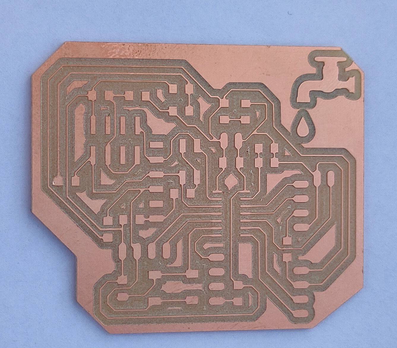
Designing the final project board | attiny1614
It was during the Input device week that i designed my final project board. I had tried all the devices that i was going to use in my final
project with Arduino UNO but i still hadn't decided whether i wanted to use the PIR motion sensor or ultrasonic sensor to detect the human
presense or whether i wanted to use step response or Control Board with LM393 Voltage Comparator to detect the running water. So while designing
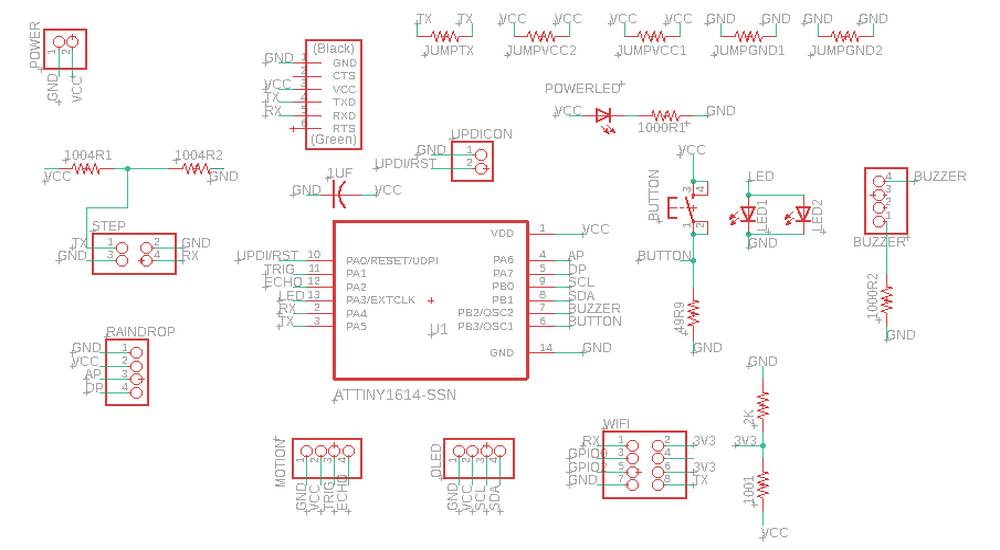
the schematic, i gave the provision for step response as well as the Control Board with LM393 Voltage Comparator. I assigned four pins
to detect the human presense so that i can use either of the PIR sensor or ultrasonic sensor. Here is how my schematic looked like,
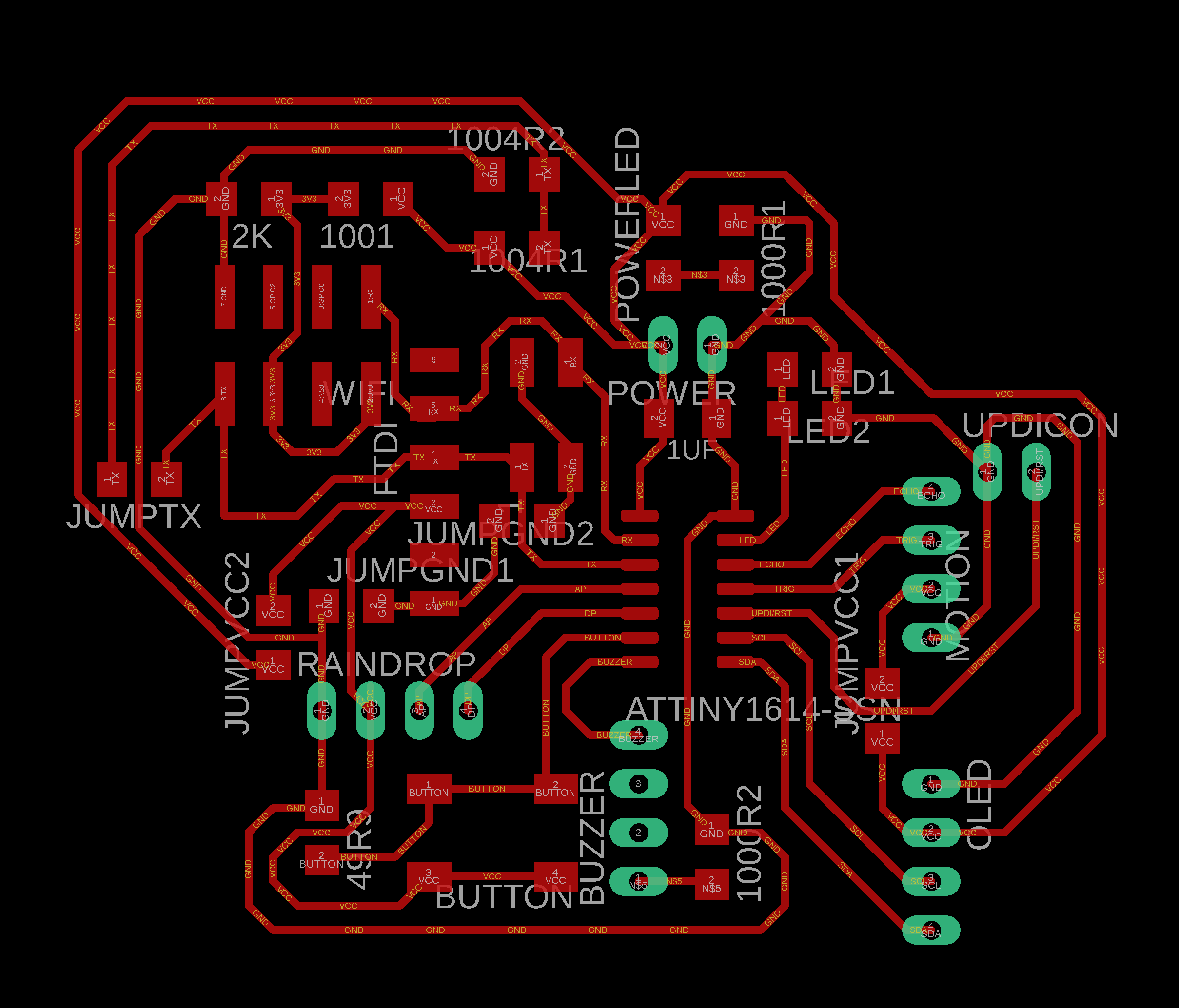
Here is how my board looked like,
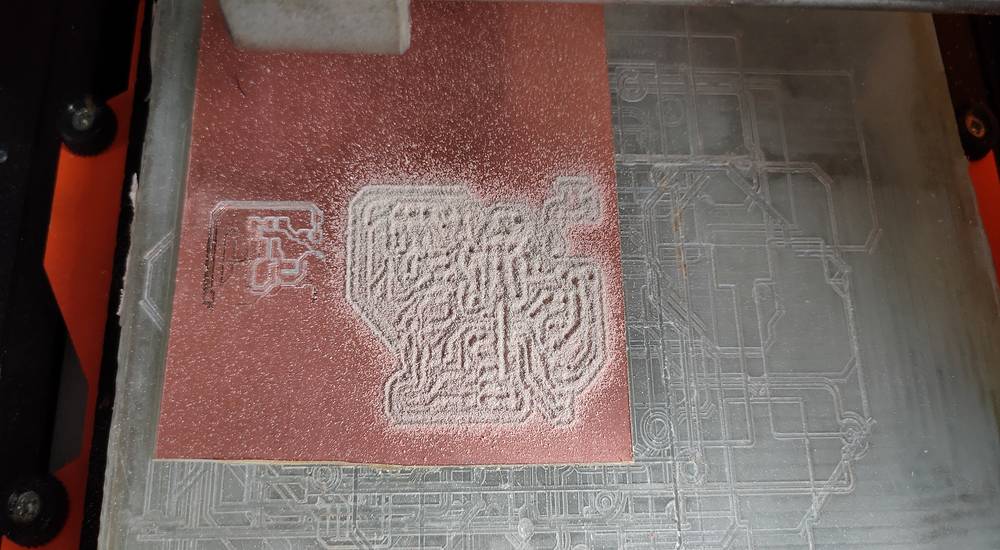
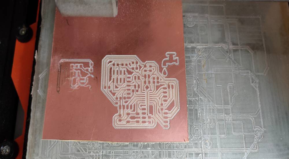
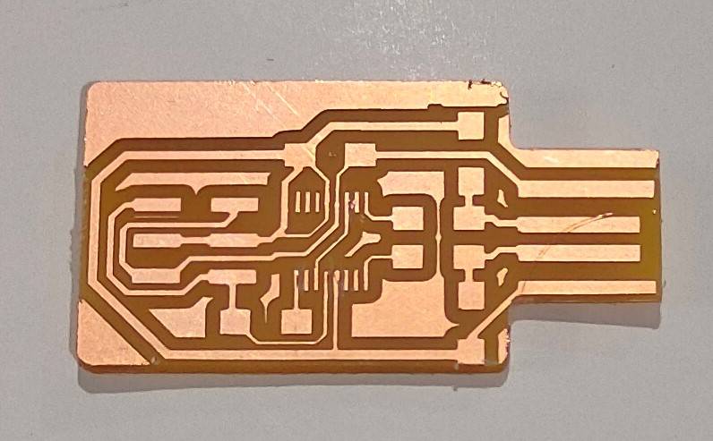
Here is how my final project board looked like after milling,
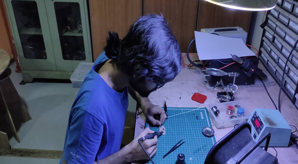
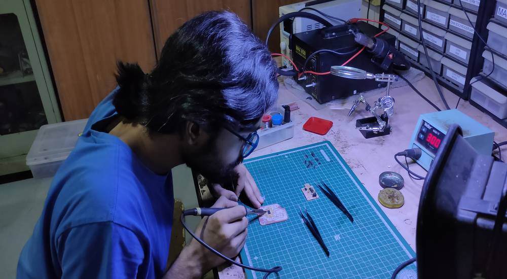
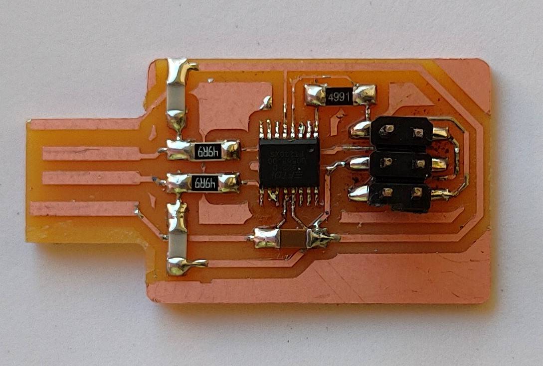
Here is how my final project board looked like after soldering,
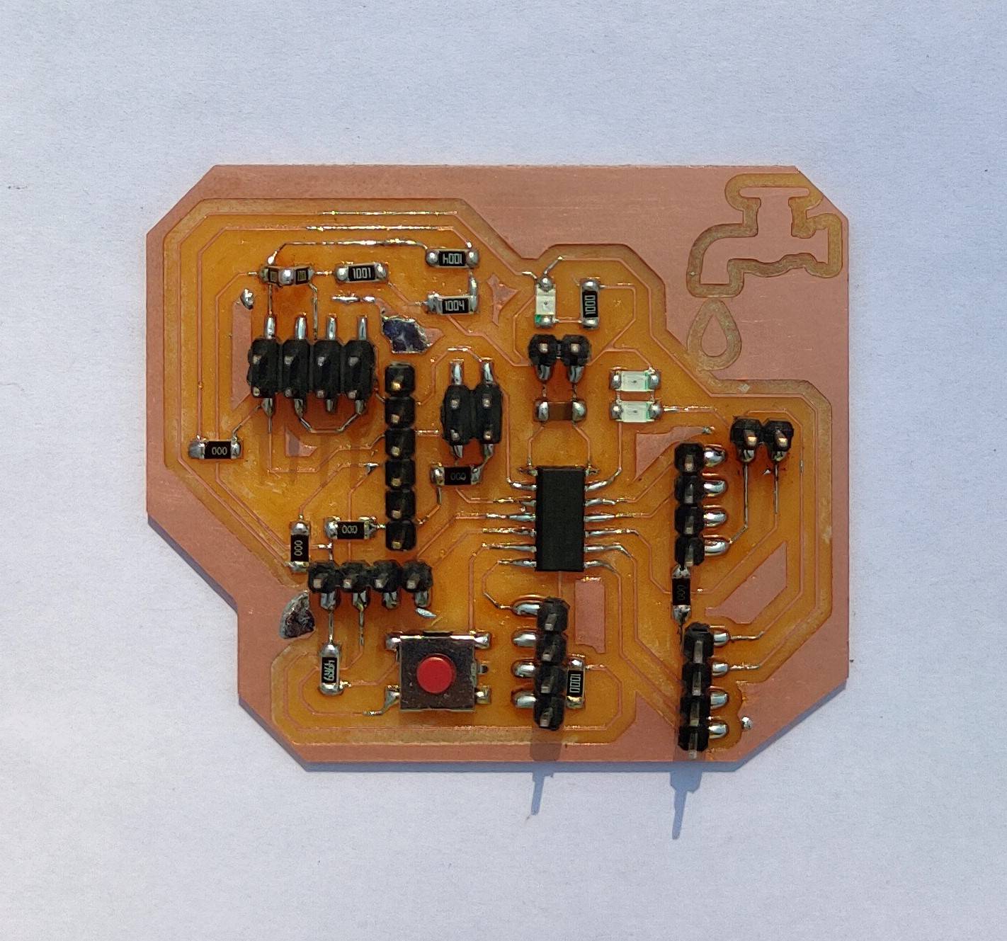
during testing all the components, i accidentally removed two header pins along with the traces. So i had to short the traces of the UPDI pin
onto the unwanted copper pad and soldered a screw connector there,
After the final project board was ready, it was time to make a programmer through which i can program my final project board. I first tried
to make the programmer with SAMD11C ic but i was not able to install the bootloader. I then decided to make another programmer with FT230XS
ic which is pre-programmed. Here is how my programmer looked like,
You'll find more details about designing the board in input device week's tab.
Testing all the devices onto the final project board | attin1614
After the final project board and the programmer was ready, it was time to upload a program to see if both the board works and then test
all the components. I uploaded a example code-blink from the arduino IDE and it was uploaded successfully in the first try,
With the final project board and programmer working i started testing all the components,
OLED
Here is the code i used to display text in the OLED with the attiny1614 board,
you can copy the code from here too.
and here is the outcome of the code,
Ultrasonic sensor
I tested ultrasonic sensor and PIR sensor one by one. However i found the PIR sensor to be very unreliable. It sometimes detect even the
slightest of the movement instantly and sometimes it just won't give any feedback. Sometimes after detecting the movement, it will give some
feedback very late so i was more comfortable with selecting the ultrasonic sensor as the device to detect the human presense.
Here is the code i used for the ultrasonic sensor in action with attiny1614,
you can copy the code from here too.
and here is the outcome of the code,
Step-response
In the step response there are two electrodes. A series of pulses is sent through the TX electrode and the RX electrode will be connected
between two resistors, one for pull-up and the other for pull-down and to an analog input.It can be used to calculate the value
of force, weight, resistance. You can read more about step response from here: http://fabacademy.org/2020/labs/leon/students/adrian-torres/adrianino.html#step
So as as you put the weight onto the two electrodes, the value increases and if you just connect the two electrodes, there will be huge change
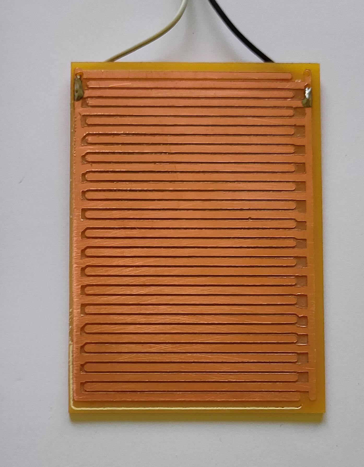
in it's values. With the same principle i designed a replica of the rain drop sensor where there are two set of traces,
The two pins from this pad is connected to the RX and TX of the step response and when the water will fall onto the pad, making the connection
between the two traces there will be changes in the value and using that readings we can define whethere there is running water or not.
Here is the code i used for step response with the attiny1614 board,
you can copy the code from here too.
and here is the outcome of the code,
As you can see in the video, the readings before any contact was around 24000 which jumperd to 32000 when water dropped onto the pad making
connection between two traces.
Control Board with LM393 Voltage Comparator OR YL-69 soil moisture module
The YL-69 module or the Control Board with LM393 Voltage Comparator measures the resistivity or DC conductivity. If you see the YL-69 module,
it has GND-VCC-AO(analog)-DO(difital) pins on one end and two electrodes on the other end. When the two electrodes gets into contact, the resistivity
decreases. I attached the PCB with two sets of traces that i designed with the two electrodes pin on the YL-69 module.
At the time of recording, i was using the AO(analog pin) of the module so that when the water makes contact between the two traces, you can
see the analog reading instead of just 1 and 0 or high and low.
Here is the code i used for the YL-69 module with the attiny1614 board,
you can copy the code from here too.
and here is the outcome of the code,
The readings you see in the serial monitor is the value of resistivity. So when there was no contact between the traces, the values were 1023
which decreased to around 520 when the water drop made the contact between two traces. We can use these readings to detect the running
water.
In the step response, i just need two resistor to detect the running water while on the other hand i need a separate YL-69 module to detect the
running water, so i decided to use the step response for my final project.
You'll find the details regarding these devices in detail in input devices tab.
esp8266-01 and esp8266-12e
I first tried to blink a LED with the esp8266-01 module with the Arduio UNO board. With the help of blynk cloud, i was able to control the LED
through the blynk app and server. However there were some issues with installing te AT firmware and i found that the responce of the LED with
the button in the blynk app/server was not very responsive.
Here is the code i used for esp8266-01 with the Arduino UNO board,
you can copy the code from here too.
and here is the outcome of the code with esp8266-01 module,
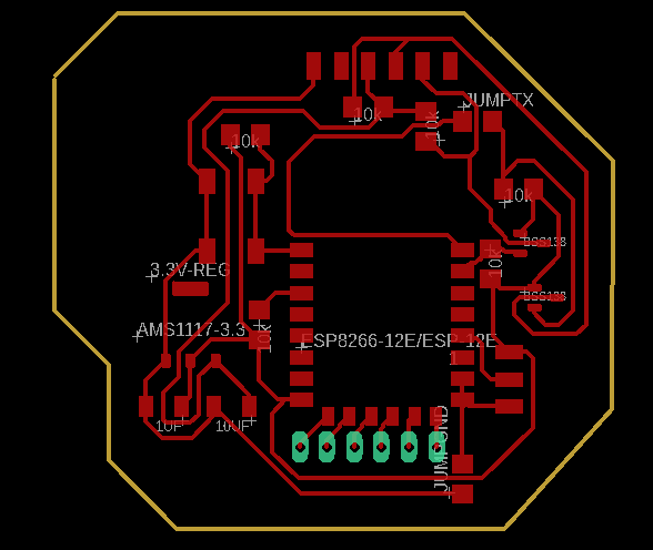
I shared all these things with my other local instructor and as per his instructions, i made a board with esp8266-12e IC which would act as
a wifi module. Here is how my schematic and board file for the esp8266-12e board looked like,
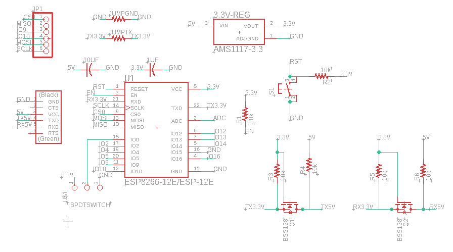
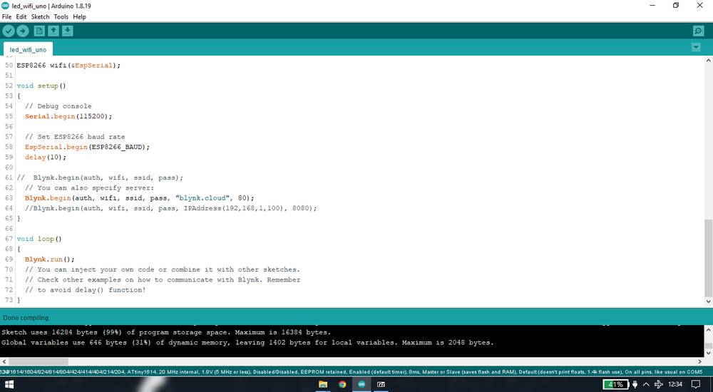
I used the same code for the esp8266-12e board that i used for the esp8266-01 module
and here is the outcome of the code with es8266-12e board that i made,
I was eble to turn the led on and off with the blynk app/server but the results were same thati got from the esp8266-01 module where the led was
not very responsive. When my local instructor selected attiny1614 as the board in the arduino IDE and compiled the sketch, it was then that i
was being told that the sketch for blinking led itself was taking 99% of the storage,
After spending a month worth of time behing making the attiny1614 board, programmer with SAMD11C and FT230XS IC, testing all the components onto
the attiny1614 board and lastly using esp8266-01 module and then making board with esp8266-12e IC that acts as a wifi module, i had no option
other than switching the IC of my final project board from attiny1614 to esp32 because i didn't wat to comproise with sending the data of
drops and stream through wifi.
You'll find the details regarding the esp8266-01 module and esp8266-12e board in detain in interface and application programming tab.
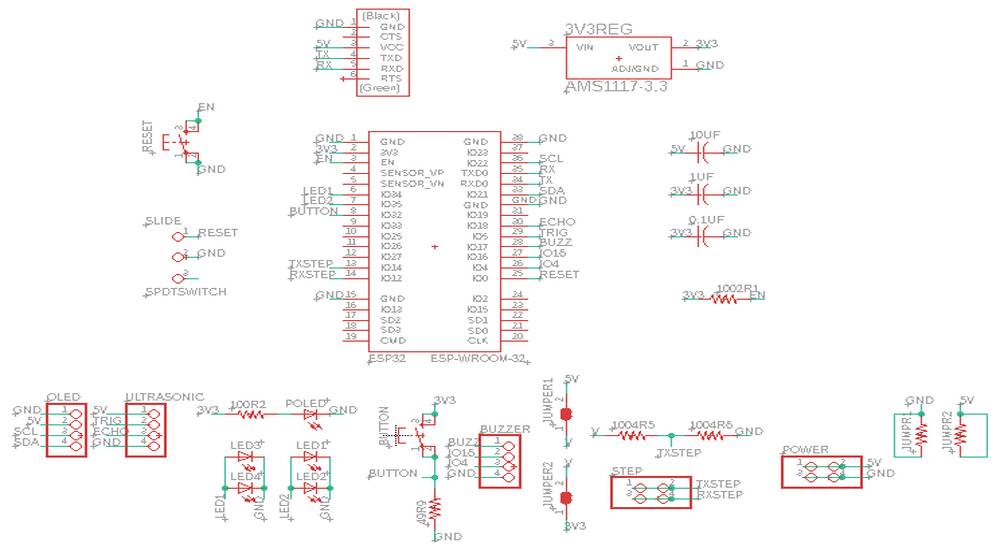
Designing the final project board | esp32
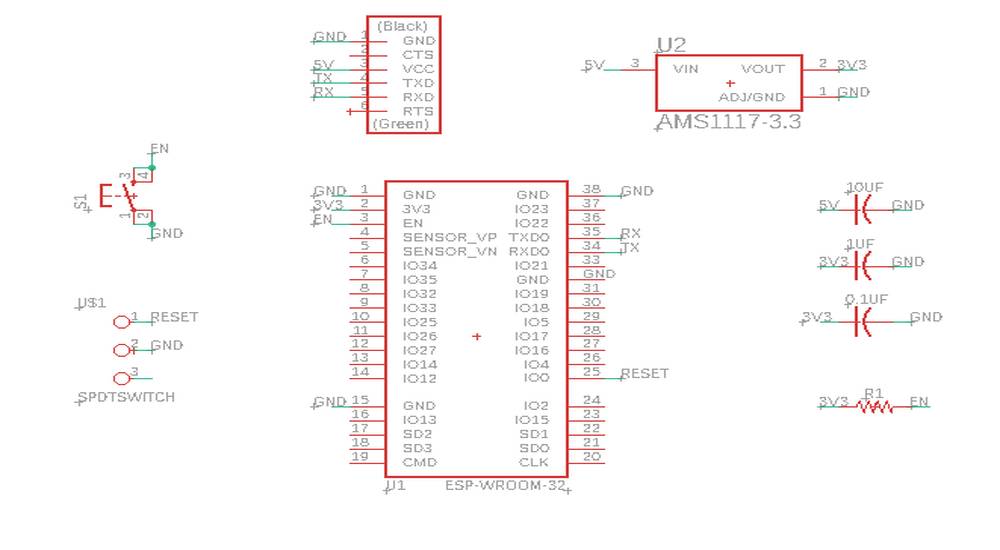
I first made the schematic with all the components required to make the echo board for esp32. This is the schematic of the components
required to make the echo board for esp32,
You can find the detail of the echo board of the esp32 and all the other IC's here: http://academy.cba.mit.edu/classes/embedded_programming/index.html
After the components required to make the echo board was added, i started giving the provision for the components required for my final project
like ultrasonic sensor, OLED, LED's, buzzer, push button and lastly step response. This time, unlike the step response in the attiny1614 board
where there were 4 pins: RX-TX-GND-GND i gave the provision for just 2 pins RX and TX. However instead of using 1x2 header pin, i used 2x2
header pins for better adhesion. Also, since esp32's operating voltage is 3.3V, i gave the provision for 2 jumpers. If i short the jumper with
3.3V jumper the step response will operate on 3.3V and if I short 5V jumpoer the step response will operate on 5V. You can see the provivion
i gave inthe schematic given below. However, when the board was milled and soldered, i didn't need to short any of the jumper because i was getting
the same reading whether i short the 5V jumper, whether i short 3.3V jumper or whether i don't short any of the jumper. Here is how my
schematic looked like,
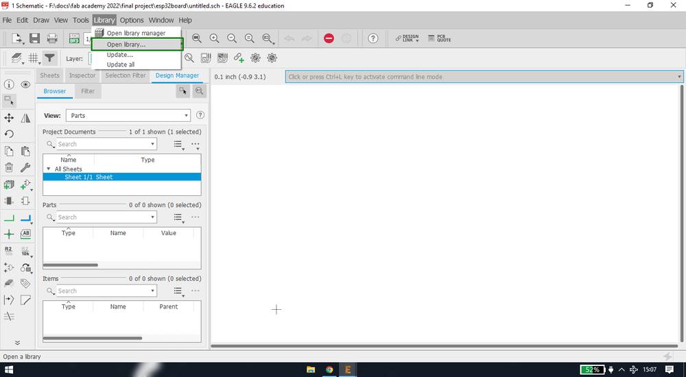
I had to change the properties of the esp32 library. Without doing that if you mill the PCB with 1/64 bit, it will short all the pads of the IC.
Here is how i changed the property of the esp32 library,
- click on library > open library
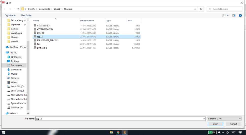
- click on esp32 library and click on open,
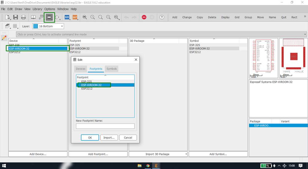
- click on ESP-WROOM-32 under device and then click on the footprint buttonon the top. A menuwill pop-up, under the Footprints tab, click on
ESP-WROOM-32 and click on ok,
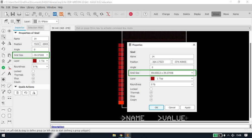
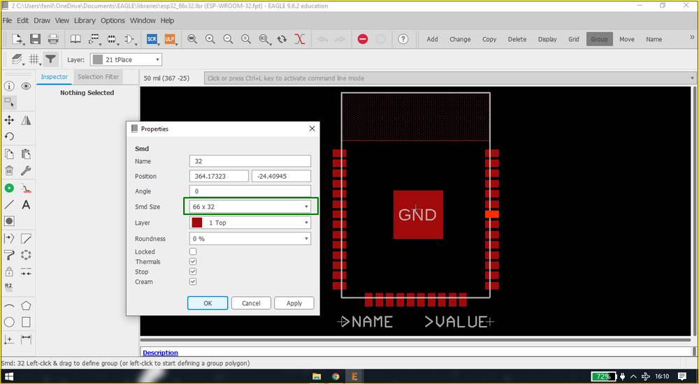
You'll be redirected to the footprint page. IF you click on any pads of the IC you'll see the SMD size on the left panel and if you right click
on any pads and click on property you'll see the same dimensionin the SMD size,
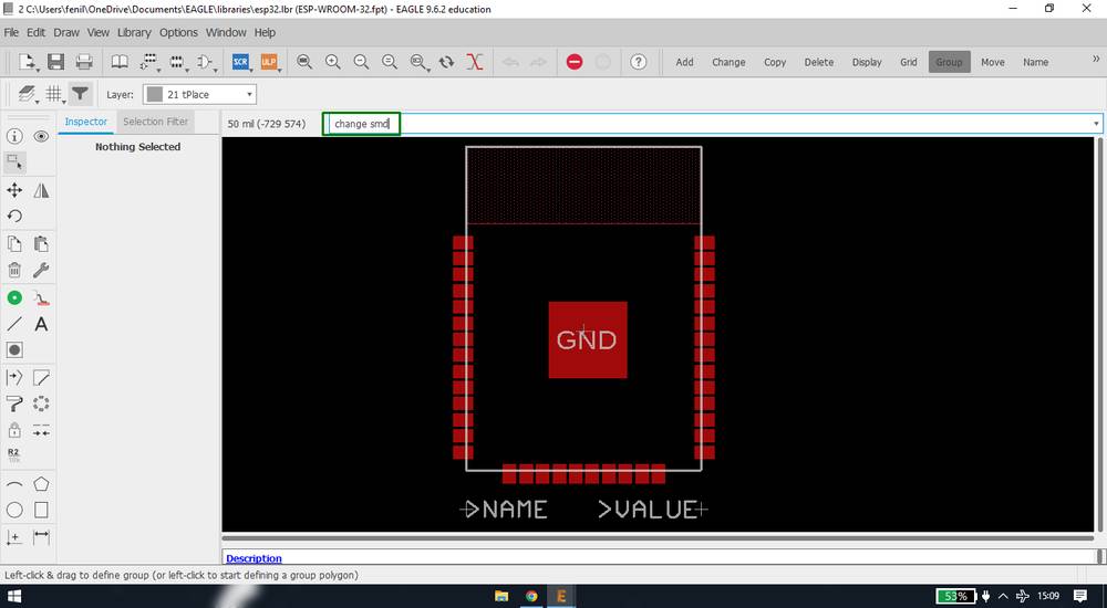
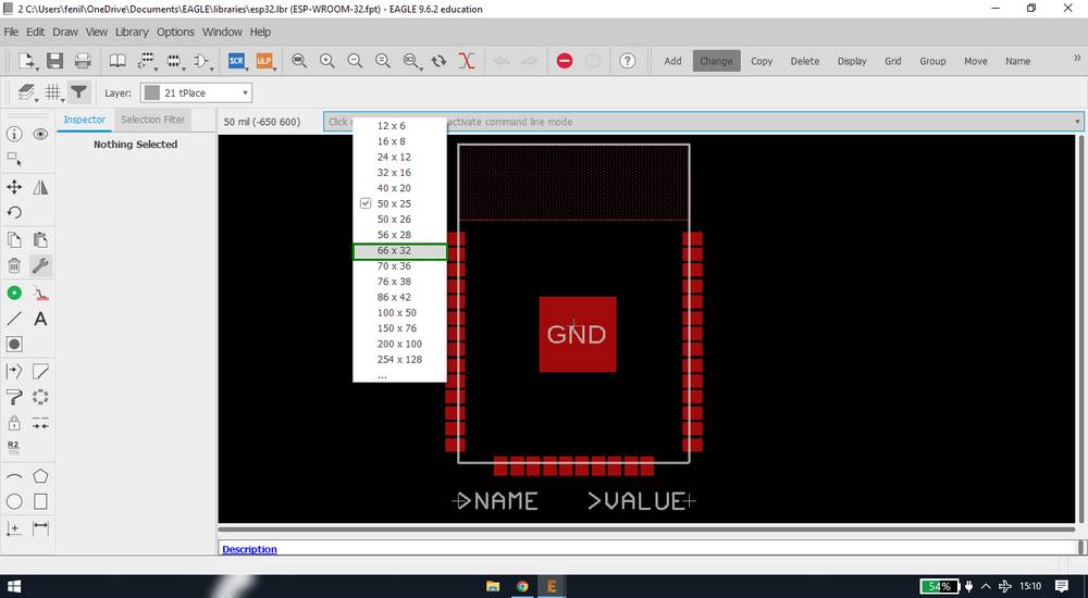
We need to change the SMD size to 66x32. To do that search change smd in the search bar and select 66x32,
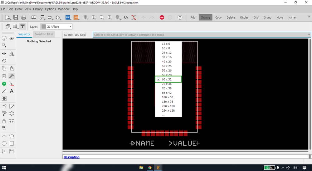
You can again search change smd to confirm that you have selected 66x32,
After selecting 66x32 as the smd size, click on each pads one by one. AFter doing that again check the property of the pad and you'll see
the size of the smd changed,
Here is the video of me changing the smd/pad size of esp32 to 66x32,
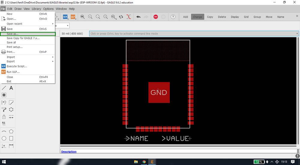
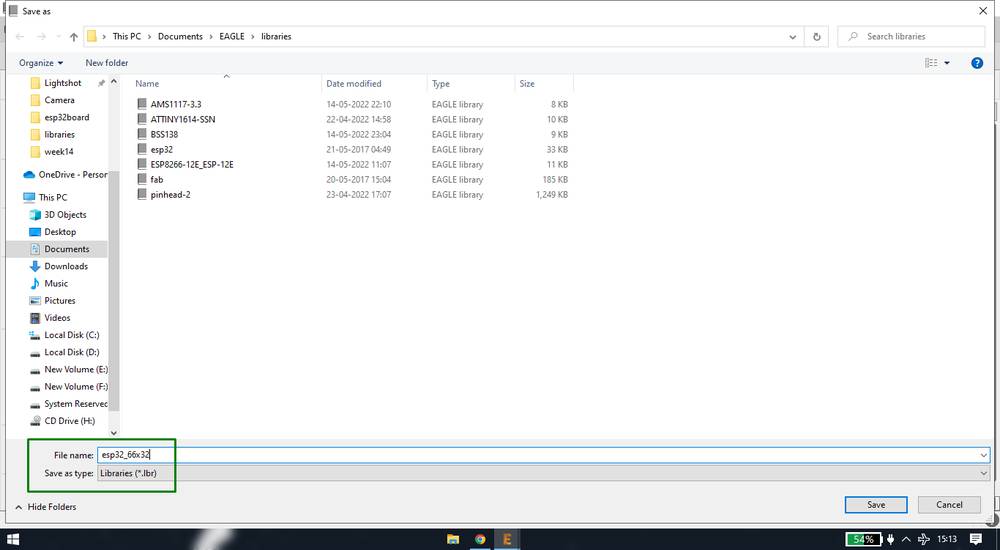
After the smd size has changed, save the library with a different name,
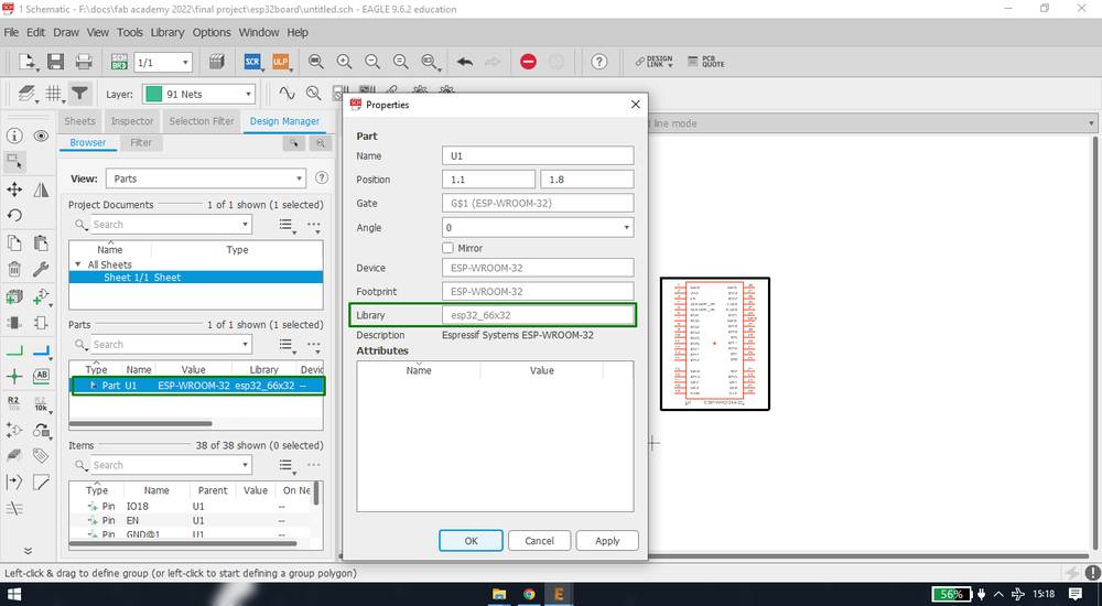
Now add the esp32 component fromthe new library you just made. To check whether the component is frrom the new library, double click on the
name under "parts" and inside the property you'll see the library name,
You can download the library for esp32 with the SMD size changed to 66x32 from here,
esp32 library 66x32 SMD size
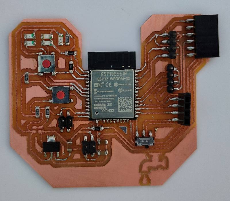
and this is how my esp32 board looks like,
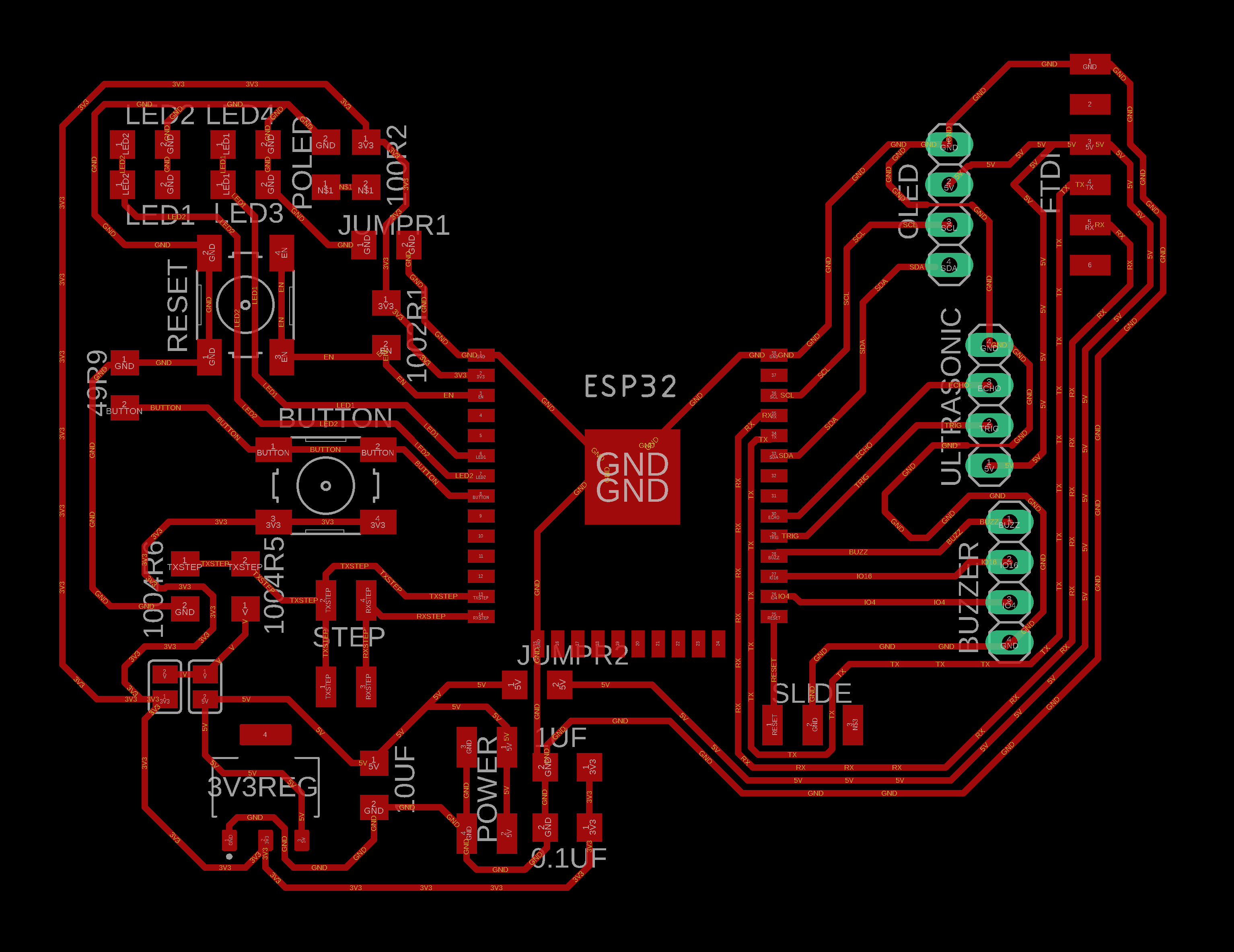
Design file for my final project board,
final project board
There were some mistakes i made while making the esp32 board,
- I gave the proviison for the LED's on pin GPIO34 and GPIO35 which are input only pins,
- I gave provision for just one push button for controlling the LED for drop and stream,
- I gave the provision for the LED's, buzzer, push button and reset button and mounted the same ONTO the final project board instead of giving provision
for the header pins or screw connector because ultimately i wanted to have the the push buttons for reset and turning the LED/buzzer off onto
the casing of the
final project board since opening the case every time someone wants to turn off the LED/buzzer and reset the board with the SMD push buttons
onto the board would be very inconvinient.
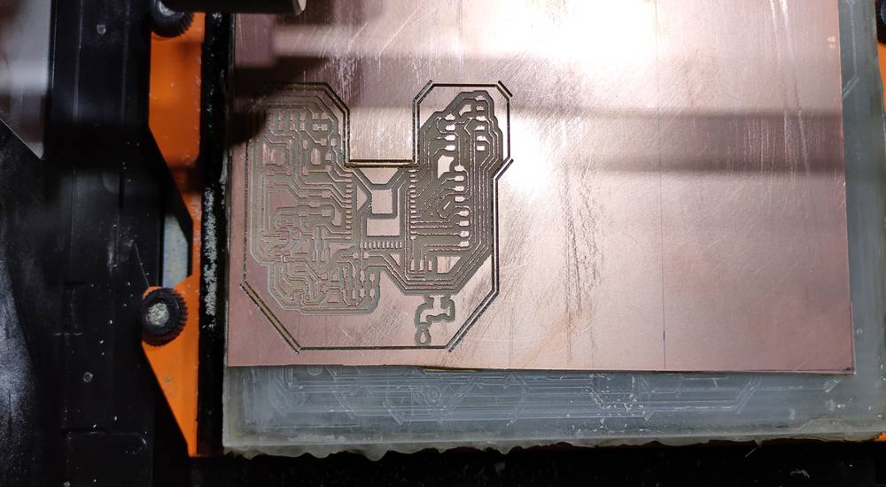
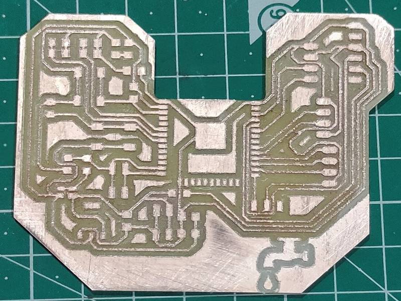
This is how my board looked like after milling, (forgot to take any video)
Here are all the components used for making the final project board,
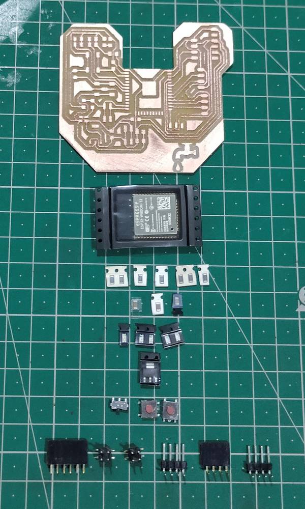
1x esp32 WROOM IC
1x AMS1117 3.3V regulator
1x slide switch
2x push button
5x LED
2x 0ohms resistor
2x 1Mohm resistor
2x 49.9ohms resistor(i used 49.9ohms resistor for the power led)
1x 10Kohm resistor
1x 1x6 female header pin
2x 2x2 male header pin
2x 1x4 male header pin
1x 1x4 female header pin(to directly mount the buzzer onto the header pin)
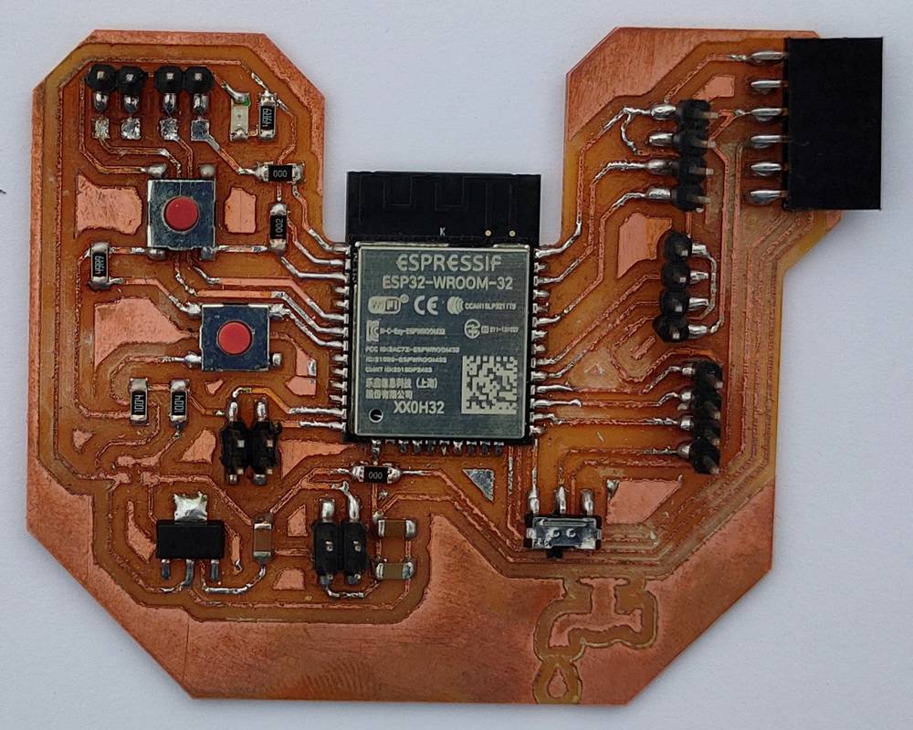
Here is how myboard looked like after solering all the components,
Testing all the devices onto the final project board | esp32
I again tested all the devices mentioned above with the esp32 board with the same code, and evey componnet seemed to work fine, execpt the
OLED. When i uploaded the code i used for my attiny1614 board there was no display of text in the OLED. I looked up online for some tutorial
and discovered this code and when i uploaded that code i was successfully able to display the text onto the OLED. Here is the code i used,
you can copy the code from here too.
Source for the code: https://randomnerdtutorials.com/guide-for-oled-display-with-arduino/
Making the water sensor
I had to make/find something that can be attached onto the two electrodes of the YL-69 soil moisture module or on the RX-TX pins of the
step response. So when the water falls onto the water sensor, it will change the values and using that readings we can define if there is
presense of water or not.
Wire mesh
As mentioned above, before joining the fab academy,
I came up with an idea to use two piece of mesh wire and separate them with a thin sheet of MDF. When i tested it, the water either doesn't
make any contatc between the two mesh wire or when it does, it gets
stuck between the mesh wire and the contact won't break until given external jerk.
because of this, the microcontroller will keep incrementing +1 in the stream even though there is no running water if the water is stuck between
two wire mesh. SO i had to come up something which has two electrodes which gets connected if the water falls on it AND the water should slip away
and not get stuck.
Rain drop like pad
So in the input device week, i made a replica of the rain drop sensor where there are two sets of traces and i designed in a way where
even the tiniest of the drop will connect the two traces. Here is the image of the pad i made,
I attached the two pins of the pad with the RX-TX pins of the step response and uploaded the step response code mentioned above and here
are the results alongwith the serial monitor readings,
If you see the video, the value before the water falls onto the pad were around 100K and when the water drop falls onto the pad making the contact
between two traces, it reached its maximum value of 137045. Since the water drop was not sliding down the pad without external jerk, it was constantly
showing the maximum value which was something i did't want.
Rain drop like pad | with vibration motor
Since the pad needed an external jerk for the water drop to slide, i thought that attaching a vibration motor might help. We had KG160 vibration motor
in our inventory which works well woth 3.3V. So i attached the motor behind the pad and was manually controllling the motor by giving
3.3V power supply from arduino UNO. Here is the outcome,
As you see in the video, the vibration motor was not helping in sliding the water drop. The water drop was not sliding whether it was on the trace
or in between two trace or whether it was getting any external jerk from the vibration motor or not.
Header pin
I saw a few videos on youtube regarding the rain drop sensor, the replica of which i made. However the PCB they were using seemed to have a very
smooth surface that hardly any water was remaining on the pad. SO i ordered one to test it. By the time it was delivered to me, i came up
with another, better idea.
I wanted a water sensor where there is no insulation below. In the pad i made and the pad that were in the market had insulation below the
conductive traces and because of that, the water needs to slid all the way down the pad.
I then came up with the idea of using header pins. So i took one set of male header pins, soldered every pins together, took another set
of male header pin, soldered every pin together and arranged both set of pins in this way, and glued them with Fevikwik
So one set of the male header pin will act as RX and other set will act as TX. It was vey fussy and a lot of space between pins were blocked
because of the glue. So i first tried to test if the water slides between them and as i thought, the water was getting stuck between them and
not sliding.
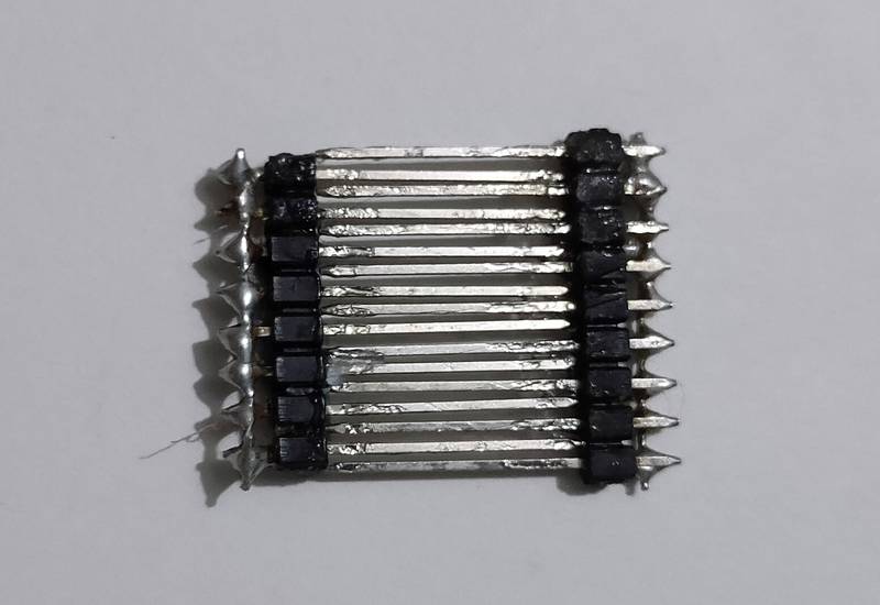
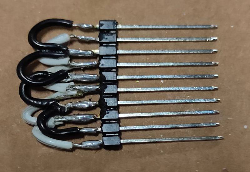
My local instructor then suggested that use only one set of male header pin and solder every alternative pins together. So solder every odd
pins together and solder every even pins together. The odd pins will act as one electrode/RX and the even pins will act as other electrode/TX.
In our inventory we had 20mm long male header pins, so i solder every alternative pins together just like i was being told. Here is how the
header pin looked like,
I then connected one odd and one even pin on the RX-TX pin of the step response and tested the code with the header pin directly under the tap
and here are the results,
If you see the video, the header pin was able to detect roughly 5/10 water drops. I thought that the reason why it is not detecting few water
drops is because my hands weren't stable and it would compensate when i fix the header pin under the tap but nonetheless this was a progress.
Screw connector and needle
After I got better results with the header pins i was searching online if i can find a longer header pin because the one i tested on was 20mm
and it was too short to mount onto the tap. I didn't find any header pins longer than 20mm, however i realised that i can find
screw connector with same 2.54mm pitch as the male header pin.
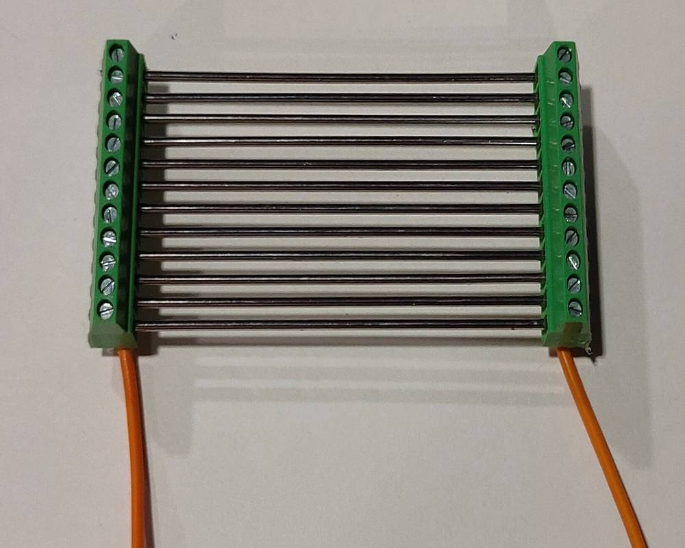
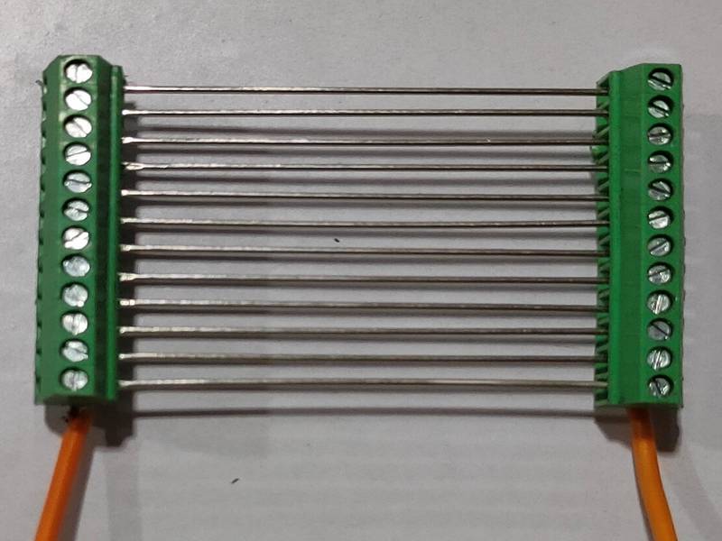
I searched online and found a 12 pin screw connector so i ordered two of them. I used needles for the screw connectors. The needles i found
were around 1.2mm in diameter which is twice compared to the male header pin but when i connect the needles into the screw connector, the
distance between two screw connector was around 55mm so i was getting a longer area forthe drop/stream to fall.
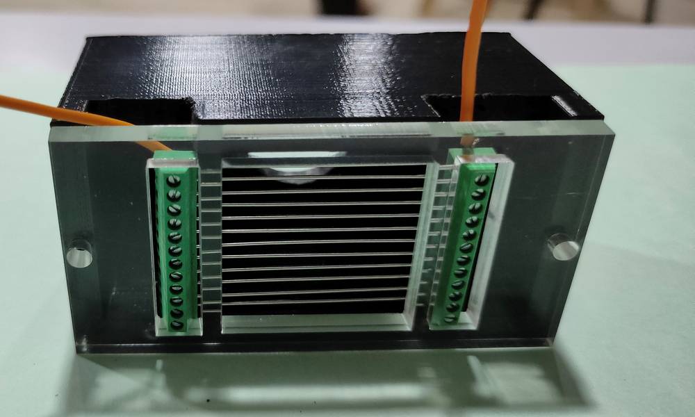
While testing the header pin, i was not sure whether the drop falling through the pins or half of the drop not getting detected was because of
my unstable hands or not and so i made a casing for the screw connector/water sensor which was suppose to directly mount onto the tap,
When i mounted the casing onto the tap and tested, i realized that since the diameter of the needle was twice compared to the male header pin
the drops were not slipping through the needles. Unfortunately i don't have any clips to show that.
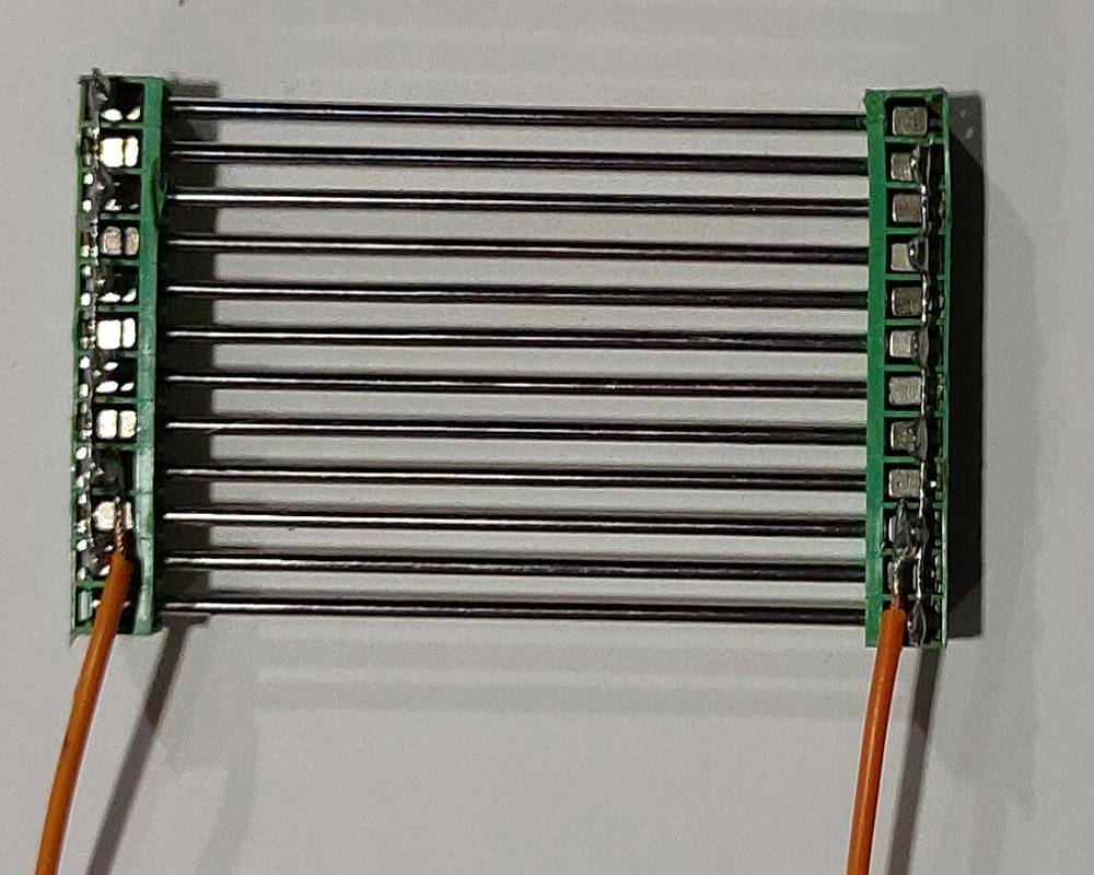
I then purchase the needles with 0.6mm thickness but i was not able to find the needle with the same length as the 1.2mm diameter one. So now
the didtance between two screw connector was around 35mm.
Since the distance between the screw connectpr reduced, i had to change the design of the bottom of the casing and also enlarge the slot
on the top of the casing. One of my colleague, Kiran Wakchaure, helped me with designing the bottom of the case and my other colleague helped
me with enlarging the slot with the help of grinder.
After the casing was ready, i mounted the casing onto the tap and tested it and just like the header pins, the water drop was slipping through
the needles most of the time and also around 5/10 water drops were getting detected. Here is the clip for that,
Programming
After all the components were tested individually with the esp32 board, it was now time to add the logic and test all the component at the
same time. As mentioned above, before joining the fab academy, i had the idea of how i want the peoject to work and my friend Mithilesh
Barasara helped me with designing the custom through hole PCB and programming.
My local instructor Suhas Labade suggested to modify that code instead of writing the whole code from scratch. Here are all the differences
between the old board with Arduino nano and the new board with esp32 IC,
- in the old board we used LDR/photoresistor to detect human presense. In the new board we are using ultrasonic sensor for detecting
human presense.
- in the old board we used LCD without I2C module, for showing the data of drop and stream. In the new board we are using OLED for showing the
data of drop and stream.
- in the old board we used two resistors to detect the runnin water. In the new board we were using step response. However, while programming and
testing the code, we were having difficulty with getting the value of m and incrementing +1s in the stream and drop so we decided to switch to
using YL-69 soil moisture module and then we were getting proper readings. We were using the digital pin of the YL-69 soil moisture module
and similarly using the digitalRead command in the sketch.
This is the code for the old version of this project,
you can copy the code from here too.
My local instructor helped me with modifying the code for the esp32 board. Here is the first version of the code,
you can copy the code from here too.
Here is a brief explaination about how the code works,
We set the ultrasonic range to 10cm. So if the readings of the ultrasonic sensor is less than 10cm, esp32 won't increase the value of "m".
Here is what the numbers in serial monitor means,
- when the two electrodes of the YL-69 module gets connected, the value of "m" will start increasing, if the readings of ultrasonic sensor is more than
the value set in the sketch.
- the value beside the value of "m" is the reset cycle. The reset cycle which is set to 60 only afftects the situation of stream, so after
incrementing +1 in the stream the value of
"m" will be 0 again. The new cycle of "m" will again start increasing after the value of reset cycle has reached 60.
- the value on the second line is the resistivity of the soil moisture module. Since i have connected the digital pin of the soil moisture,
the seria monitor will show the number 1 is there is no connection and will show number 0 if there is connection betwen the two electrodes.
- the value on the third line is the readings of the ultrasonic sensor
- the value on the fourth line is the incremented value of stream
- the value on the fifth line is the incremented value of drop
if the reading of the ultrasonic sensor is more than 10cm or more than the value set in the sketch AND the two electrodes of the soil moisture
moldule gets connected, esp32 will start increasing the value of "m". If the value of "m" is constantly increasing or if the resistivity of the
soil moisture module is constantly 0 then the esp32 will increment +1 in the stream after the value of "m" has reached 50. Basically the
GPIO14 checks every 80-100 miliseconds if there the two electrodes of the YL-69 is connected. If it is connected, esp32 will start increasing
the value of "m" by +1 every 80-100 miliseconds.
if the reading of the ultrasonic sensor is more than 10cm or more than the value set in the sketch AND the two electrodes of the soil moisture
moldule gets connected, esp32 will start increasing the value of "m". If the value of "m" stops increasing in between or if the resistivity of
the soil moisture module is switching between 1 and 0 then the esp32 will increment +1 in the drop after the value of "m" has reached 50.
The readings of the ultrasomic sensor is not constantly updated. So if the readings of the ultarsonic sensor is more than 10cm or the value set
in the sketch and then a person/object is placed then the value of the ultrasonic sensor will be updated after value of "m" is reset. The value
of "m" can be reset either by incrementing +1 in stream or drop. Here is the outcome of both the situation,
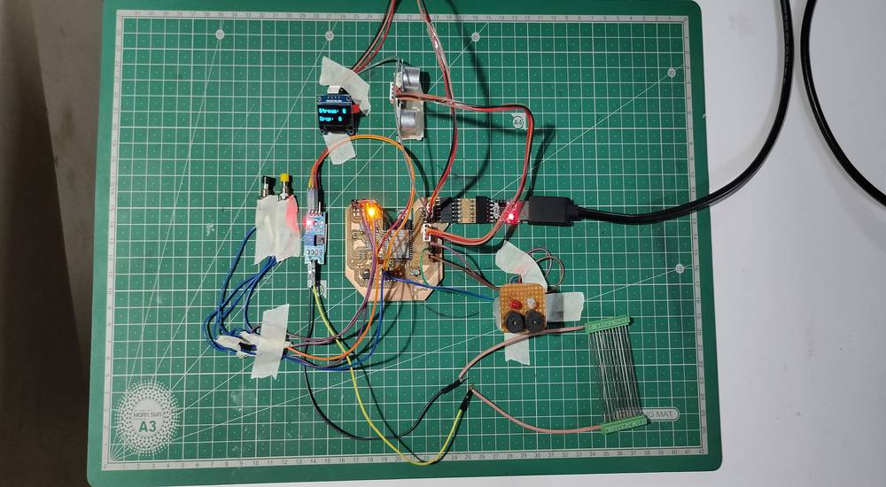
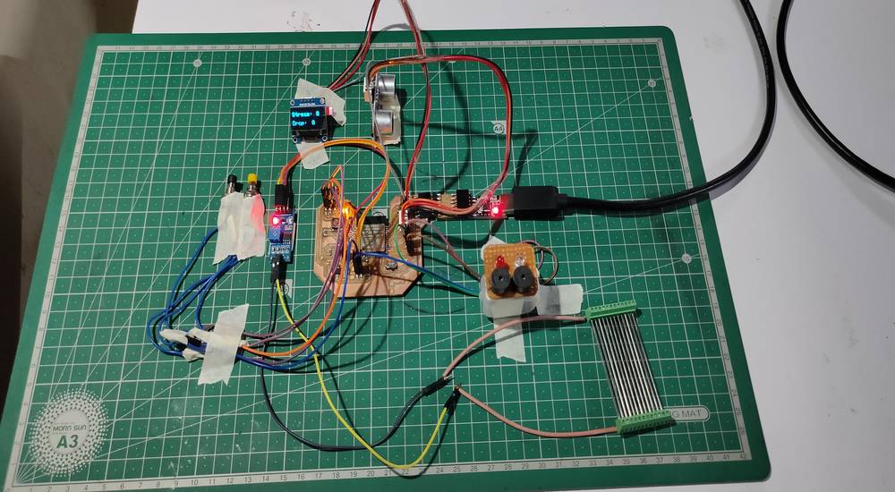
Here are some heroshots of the setup while recording all the above video,
My instructor did try to send the data of the drops and stream to the thingspeak through wifi, but we were having some issue of the delay. Instead
of GPIO14 pin(digital pin of YL-69 attached on IO14) checking every 80-100 miliseconds if the two electrodes of the YL-69 is connected, it was
checking every 4000-5000
milisedconds which was not suitable for detecting the drops. So we decided to continue working on send the data through wifi later.
Modification in the final project board | esp32
I wanted to assign separate LED-Buzzer and push button for the drop and stream so that when the incremented value of drop and stream reaches
a certain level the LED-Buzzer will turn on and the push button to turn them off. Now i wanted the LED-Buzzer and the push buttons onto the
casing of the final project board and not ONTO the final project board and so i had to do some modifications on the board. I'll explain in
brief about all the modifications i made,
- Replaced SMD LED's with male header pin, on GPIO 34 and 35
- Replaced 1x4 female header pin which was assigned for buzzer, with 1x4 male header pin.
- Short the traces of reset button with the unwanted pads nearby.
I didn't want to directly solder the wire onto my final project board and that is the reason why i gave/managed to gave the provision for
male header pins for all the 3 push buttons(2 for stream and drop and 1 for reset) and 2 LED-Buzzer, so while wiring i had to solder the LED-buzzer
and push button with the male header pin instead of directly soldering onto the pads on the final project board.
Note that i did the same wiring for the push button that was suppose to fit onto the casing as i did with the SMD push button, but instead of
using 100ohms resistor i used 5.6Kohms resistor as a pull down resistor.
Here is how my final project board looked like after the modifications,
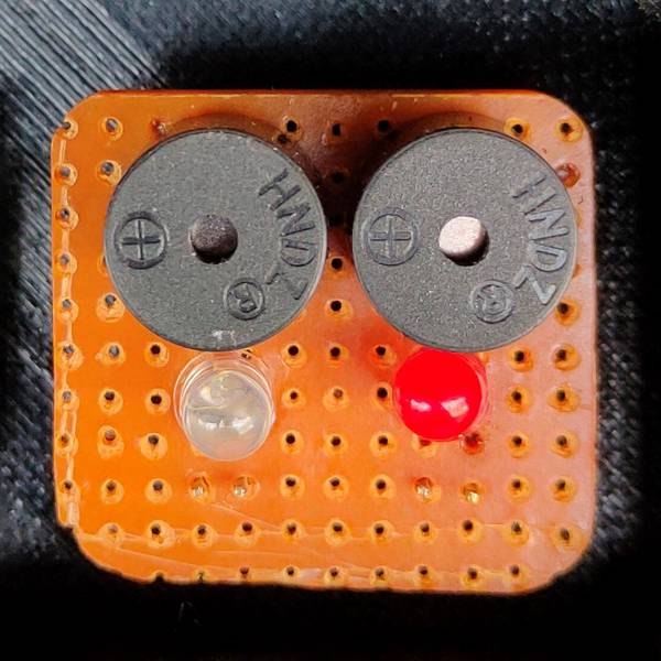
I made a small through hole PCB where i connected 2 set of LED and buzzer parallelly. One set of LED and buzzer for drop and other set of LED
and buzzer for stream,
Programming the final project board continues
After the modifications onto the final project were done, so that i can connect the LED-buzzer and push button to turn them off, i made some
changes in the sketch. The first verison of the sketch had the code of lines where the LED-buzzer will turn on after the incremented value of
drop and stream reaches a certain value, but privision of the push button turning the LED off was removed while modifying the code. So i added
that lines and changed some values and changed the names like replaced "m" with water value and this is how the second verison of the code
looks,
you can copy the code from here too.
I defined the value of drop to 2 so the LED-buzzer will turn on after the incremented value of drop reaches 2 and i defined the value of strwam to
3 so the LED-buzzer will turn on after the incremented value of stream reaches 3. Here is me testing the situation of drop,
And here is me testing the situation of stream,
Some more testing and debugging after i gave the wrong connections to the push button,
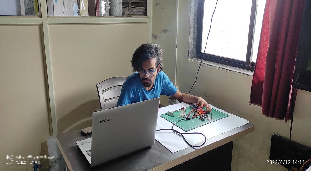
Some hero shots of the setup and me while testing the sketch,
Earlier i tried to turn off the both the LED-buzzer with just one pudh button, but it was behaving very wierdly,
This is the code i used for controlling both the LED-buzzer with just one push button,
you can copy the code from here too.
Source of the code: https://stackoverflow.com/questions/56712430/how-do-i-tell-the-code-in-arduino-if-i-press-a-button-twice-with-interrupts
What is suppose to happen is that when the push button is pressed once then red led should turn on. When the push button is pressed twice then
green led should turn on. Here is the outcome of the code,
if you see the video you'll observe that sometimes when i press the push button once, green led turns on instead of red led. In the last
the led did behaved like i wanted but i can't afford to have errors so i decided to use separate push buttons for both LED-buzzer.
After the LED-buzzer were turning on after the drop and stream was reaching a define value and i was able to turn off the LED-buzzer with
push buttons too, the only thing that was remaining was to send the data of drop and stream to thingspeak through wifi.
Two of my instructors, Suhas labade and Suvarna Sawant help me with complete programming of sending the data of drops and stream to thingspeak
through wifi. This is the third version of the code where the incremented value of stream and drop is sent to thingspeak after +1 is
incremented to drop or stream,
you can copy the code from here too.
And this is the code in action with the water sensor attached directly under the tap,
Making the cases
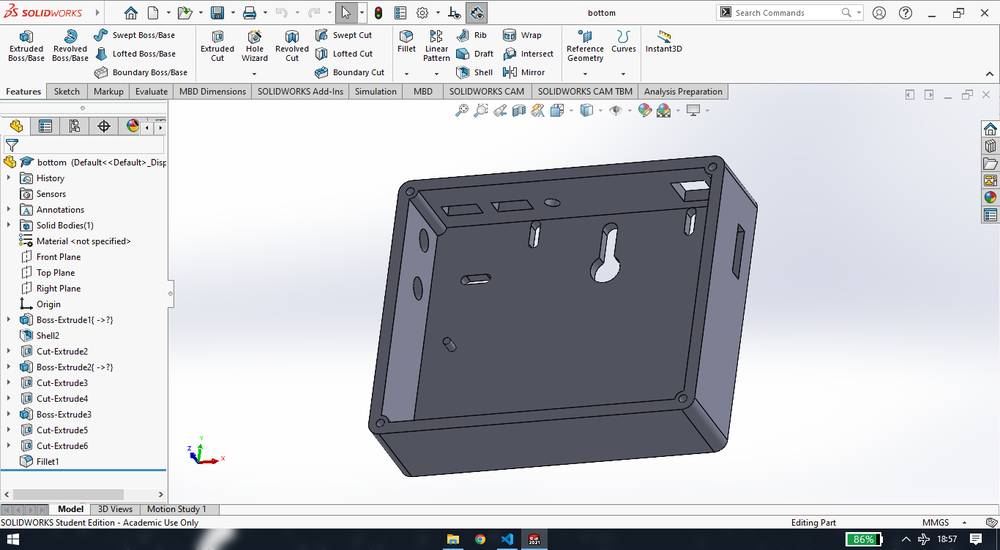
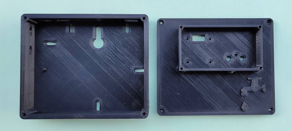
After the electronics part was functioning well, it was time do start working on the packaging. I first made the case for the final proeject board
keeping in mind that on the inside of the case i had to put my final project board and YL-69 module and on the outside of the case i have to
fix OLED and the through hole PCB with LED-Buzzer. I first made a design of the case in solidworks and also printed the top part of the case
but before printing the bottom part of the case which was going to take around 20Hours, many of my colleagues commented that the case i made
was unnecessarily bulky. Even i was not happy with the design since a lot of other things were happening along with the designing of the case.
So i re-designed the whole case and was able to print both, the top of the case and the bototm of the case in 14 hours,
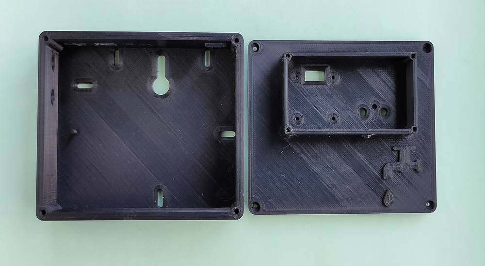
While designing the bottom part of the case, i gave the provision for push buttons, female jack for external power supply, slots for the
wire connector to go through, slots for bolts onto which i was going t fix the final project board, since the board didn't had any holes
in it, slot for the FTDI converter to go through and lastly a slot for the nail onto which i was going to hang the case. While assembling the
components i realized that i gave an extra slot for the wire connector and while programming i had to press the reset button sometimes in order
to execute the wifi connection so i had to later drill the hole into the case.
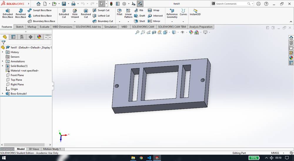
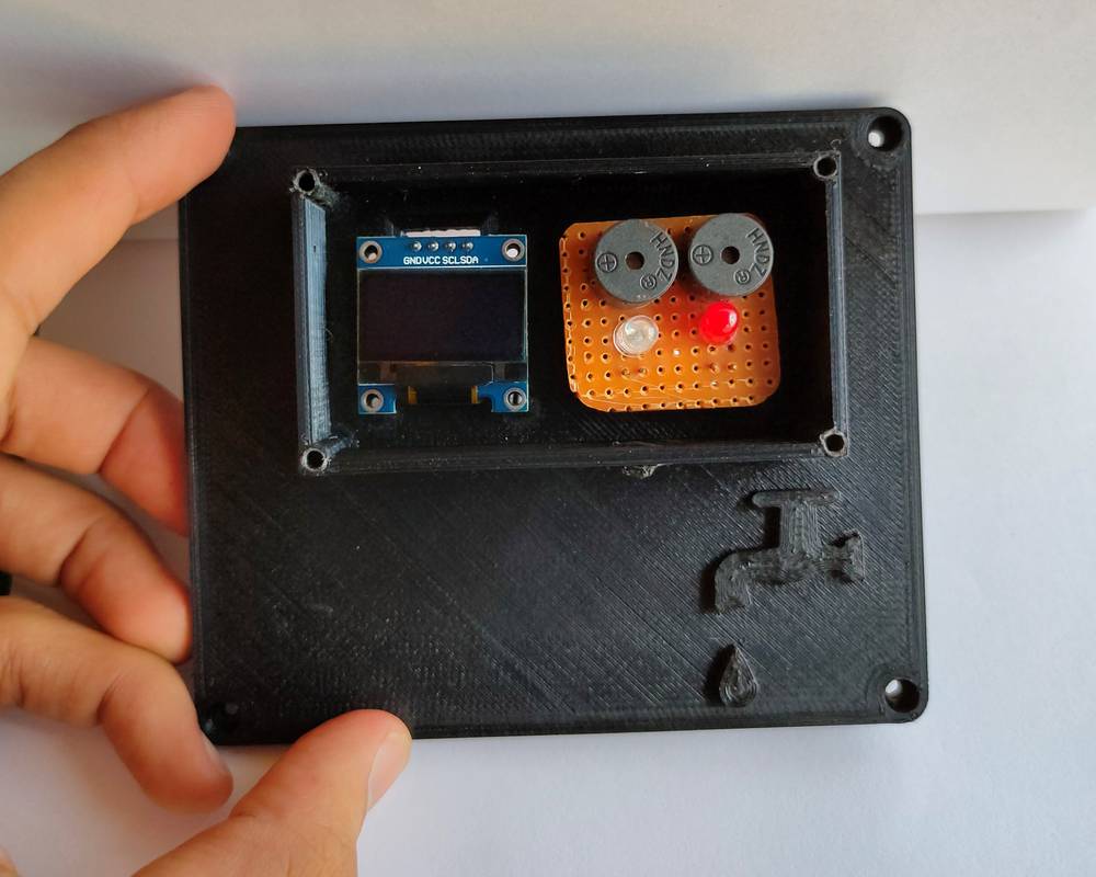
While designing the top part of the case, i gave a slot for the wire connector
that connects the OLED and i gave 2 slots for the signal and ground pins of the two LED0-buzzer. However i did not find the 2mm screw to fit the
OLED and so i used double sided tape to fix the OLED and PCB with LED-buzzer. I also designed a border so that i can cover the OLED and PCB
with some acrylic sheet to save them from dust.
Here is how the bottom part of the case looked like,
This is how my top part of the case looked like,
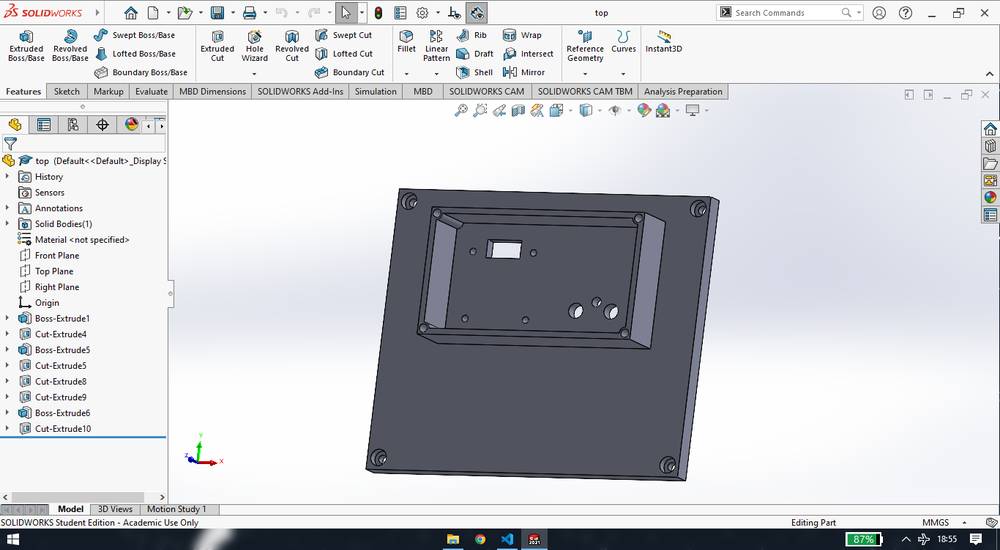
And this is how my top part of the case looked like after adding the logo of my project and adding the fillet features,

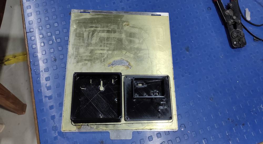
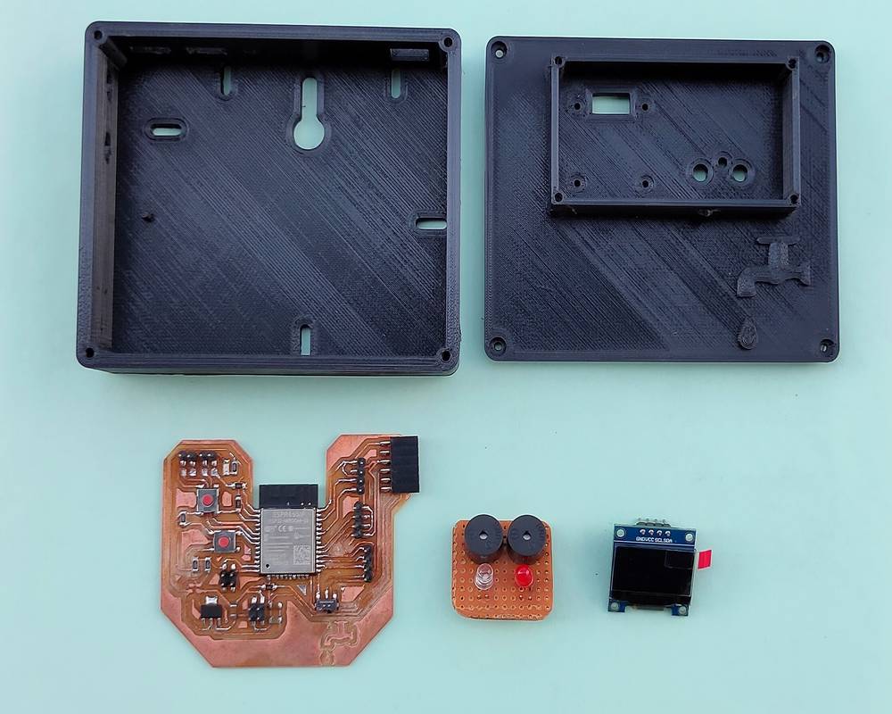
I decided to 3D print the case,
This is how the case looked like after printing,
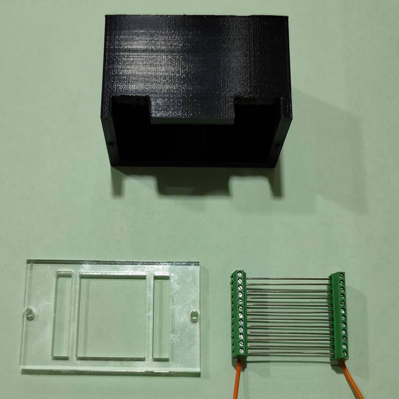
All the components that are going to fit in the case, (i forgot to take the YL-69 module while clicking the photo)
Design file for the final prject board case,
final project board case
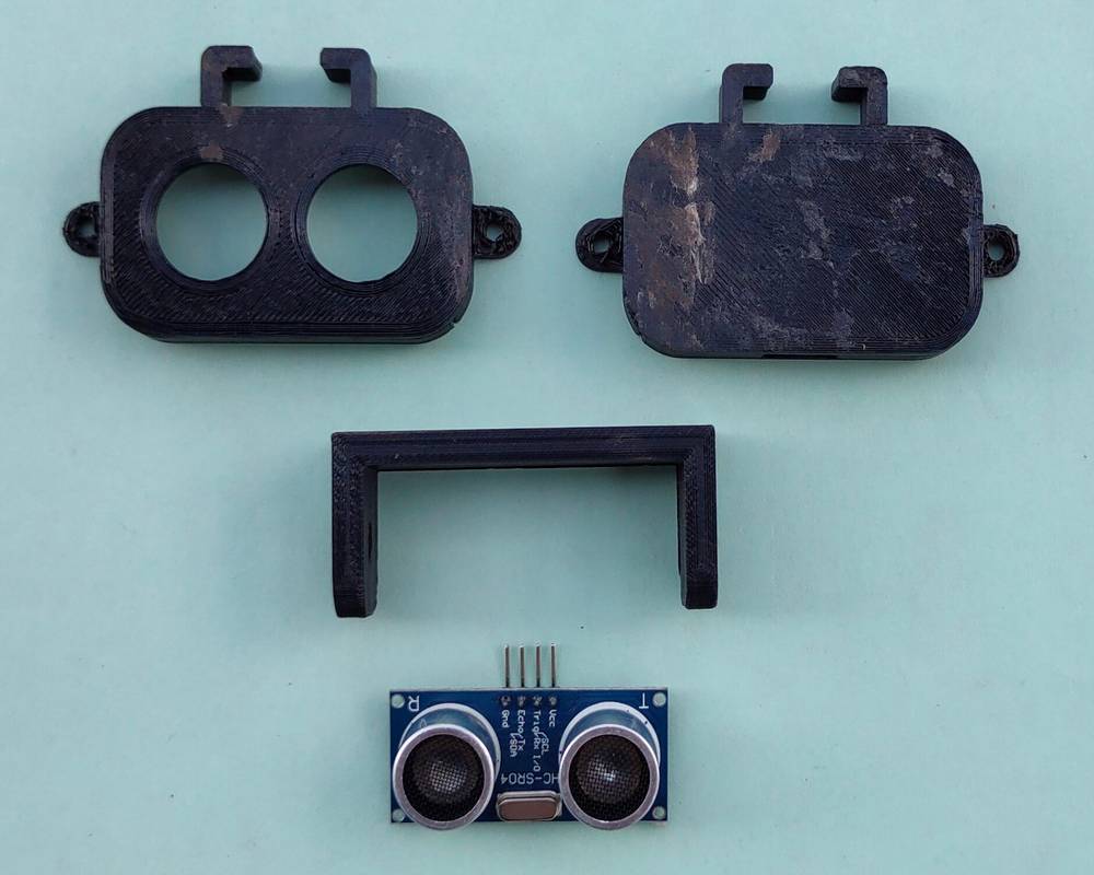
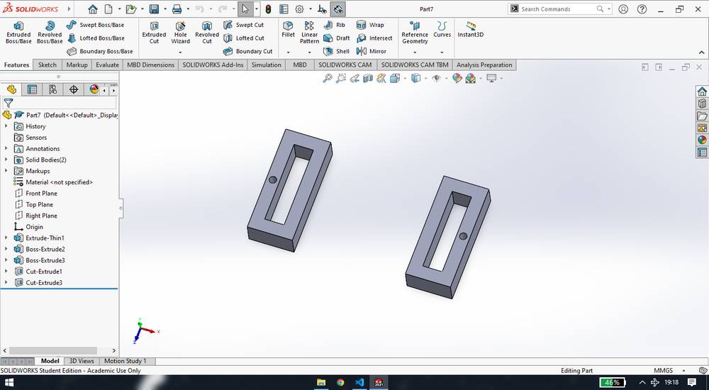
I then made the casing for ultrasonic sensor. I made the whole case, unlike the case for the final project board where i had designed the top and bottom part of the case separately, and then with the reference geometry cut extrude one side of the design and exported the STL file, undo the cutting, cut extrude the other side of the design and exported the STL file,
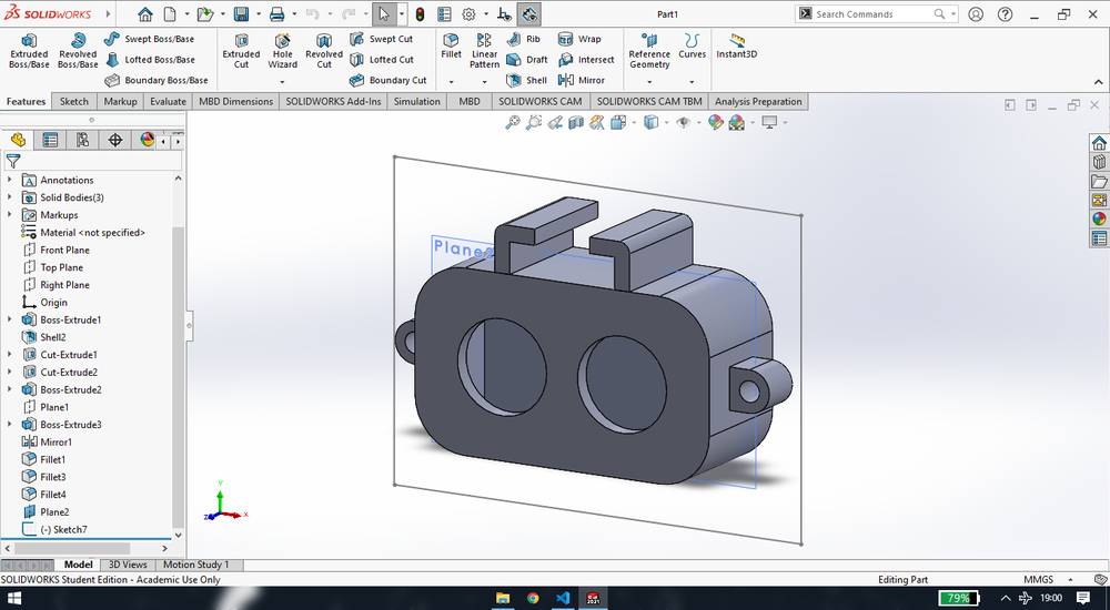
NOTE that the case i made is of loose fit and i had to stick double side tape behind the sensor to level up the sensor.
I then made a holder for that,

I decided to 3D print this case too,
This is how the case looked like after printing,
Design file for the ultrasonic case,
ultrasonic case
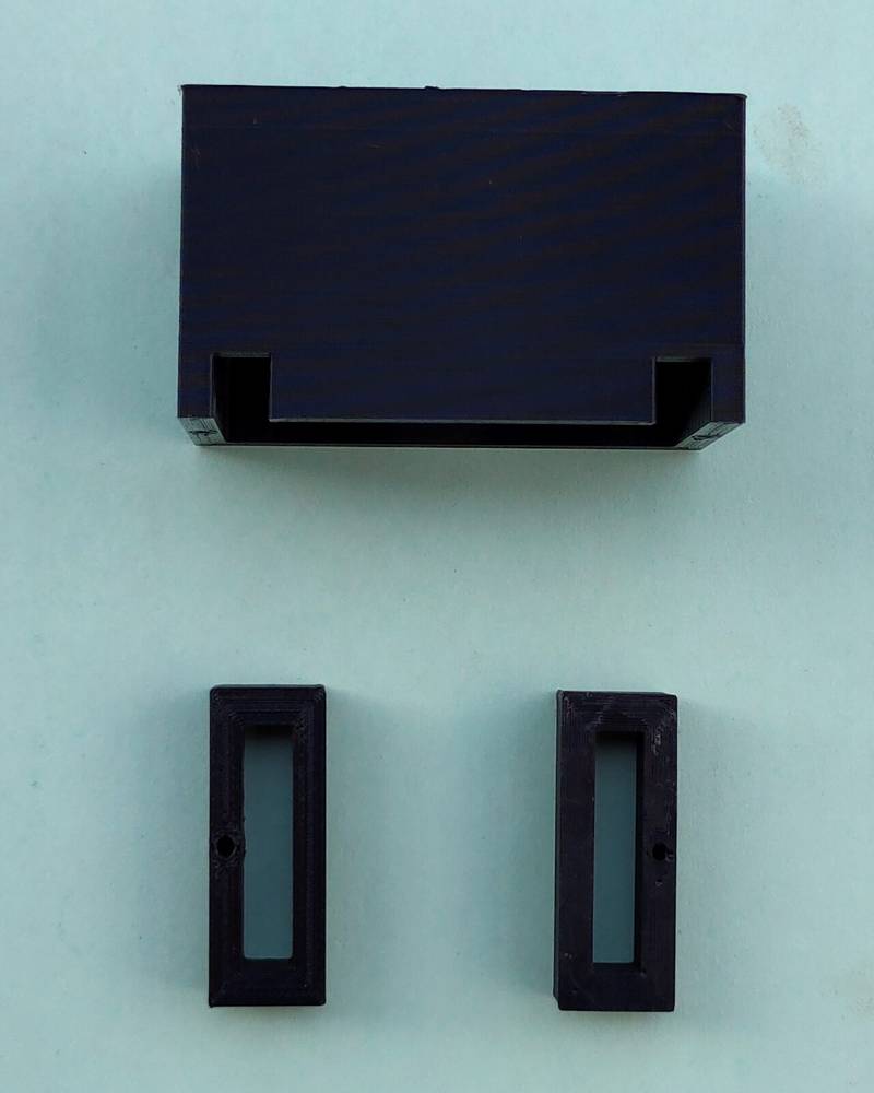
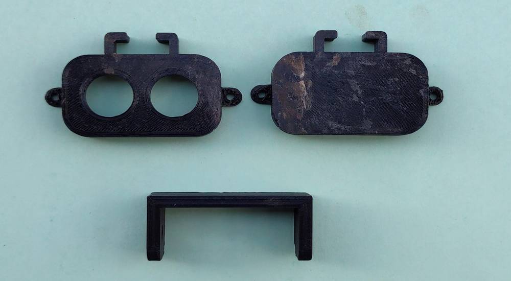
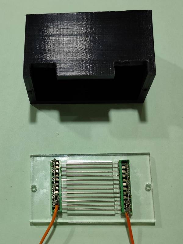
I then made the casing for the water sensor/screw connector with needle keeping in mind the dimensions with 1.2mm diameter needle inserted. This is how the top part of the case looks like,

here is how the bottom part of the case looks like,
This is how the printed part looked like,
Design file for the water sensor/screw connector w/needle case,
water sensor case
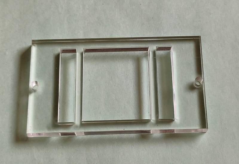
Later when the drop was not easily sliding through, i had to change the needles and the needles i replaced with were short in length. And so i had to change the design of the bottom of the case and also enlarge the slot onthe top of the case. My colleague, Kiran Wakchaure helped me with designing and cutting that part in acrylic in the laser cutting machine, and my other colleague, Ashish Shende, helped me with enlarging the slot on the top of the case,
you can download the dxf file of the bottom part of the screw connector here,
screw connector bottom part
This is how the laser cut part looked like,
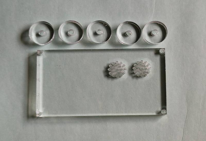
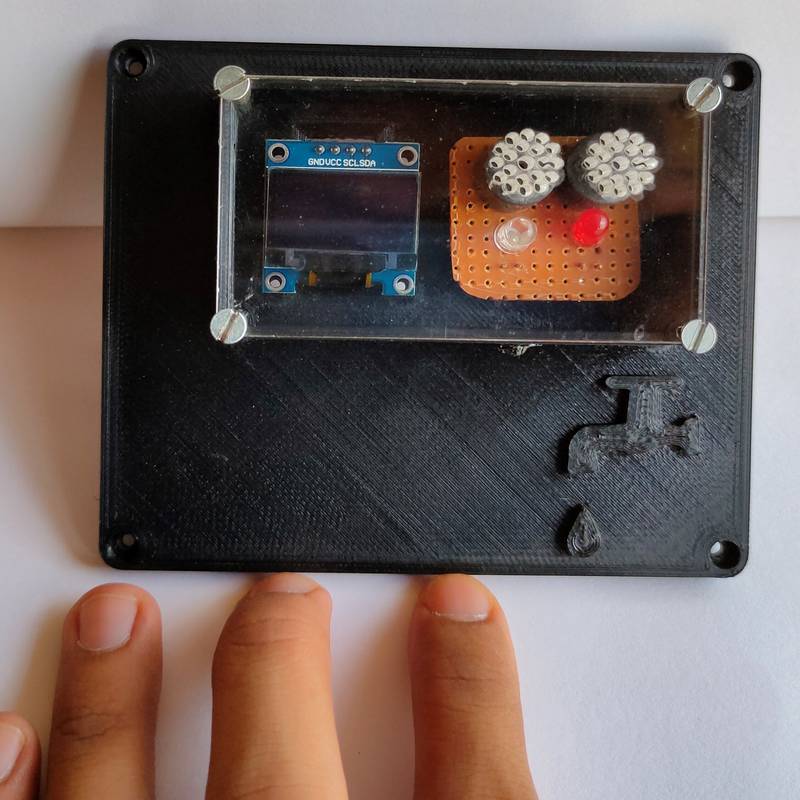
I then designed the cover for the OLED and the PCB and designed small holes over buzzer so the sound can penetrate and cut the design along with the studs/washer to fix the final project board in the acrylic in the laser cutting machine,
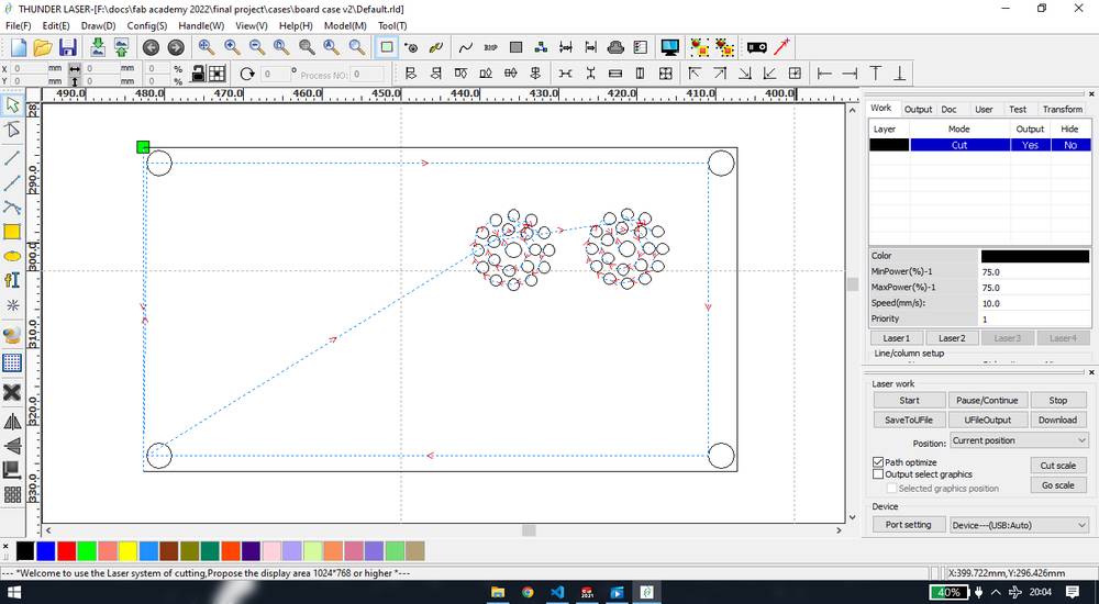
You can download the rld file here,
acrylic shield
This is how the cut part looked like,
Assembly
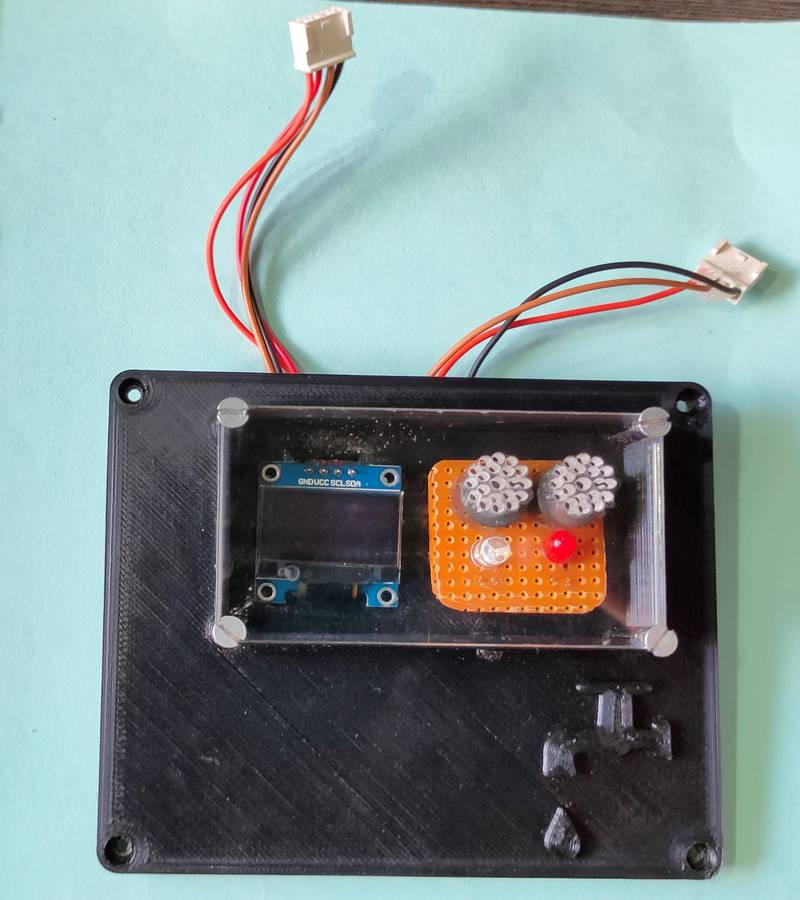
after the cases were ready, i just had to assemble everything and do some minor soldering to connect the push buttons, power jack, Oled and
PCB with LED-buzzer,
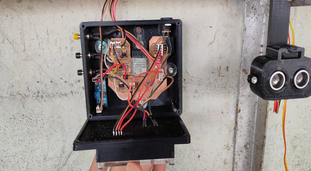
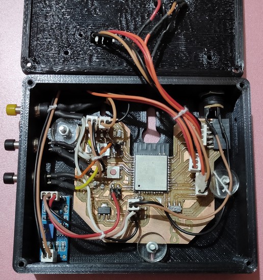
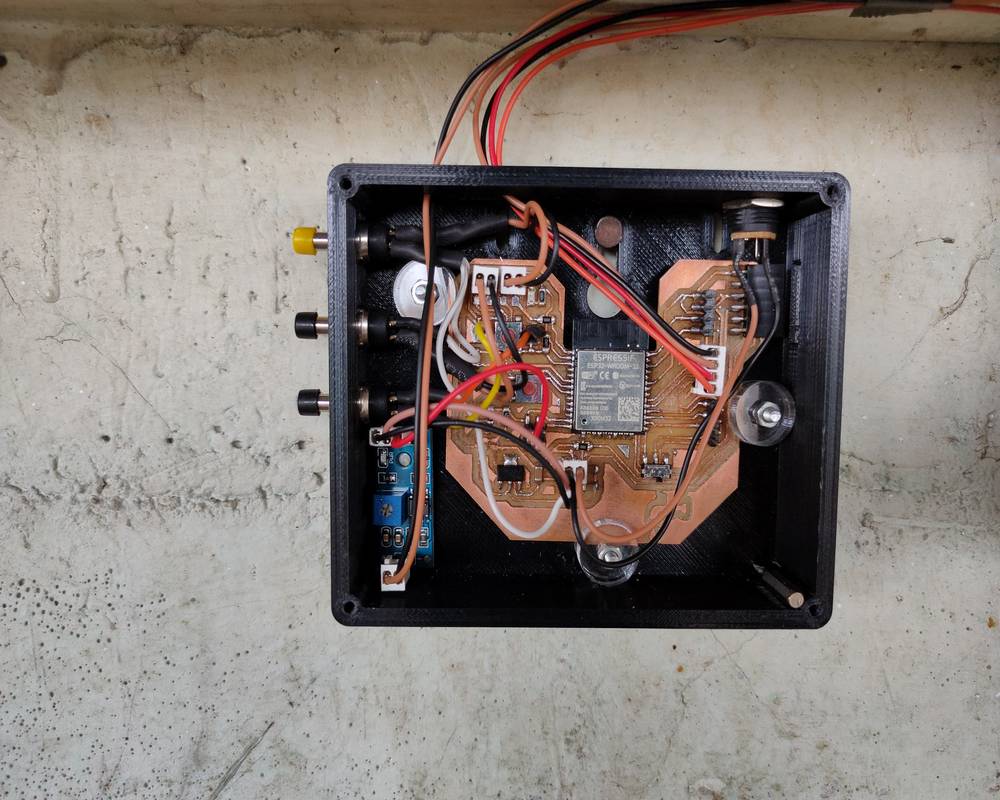
Here is how the inside of the casing looked like,
tied some thread on the wire for comparatively cleaner look, this photo was cicked later
I did the wiring in a way that i can simply open the case and get the access to the components inside, like using the slide switch while programming,
without needing to disconnect any wire.
And in case i need to remove the top part of the case it could be easily done since i used wire connector for the header pins on the board
and soldered the other end onto the push butotns, oled, power jack and PCB,
Here are some hero shot of the setup,
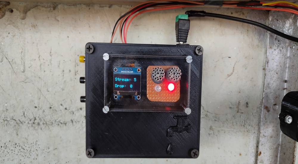


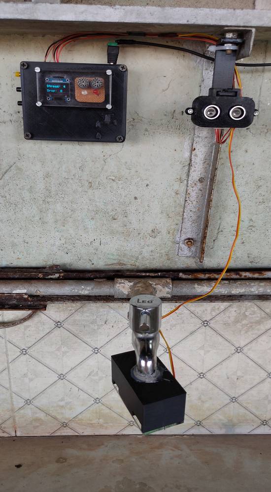
Here is the video i shot for the presentation showing the working of the system,
Solution
Bill of material
Here is my bill of material,
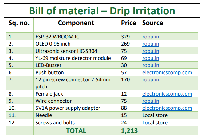
The Bill of material doesn't include,
all the SMD components used for making the esp32 board,
200 grams of filament used for 3D printing,
Acrylic sheet used for making the shield for OLED and LED-Buzzer and for makingthe studs/washer.
You can download the word file for the links of each component from here:
Bill of material
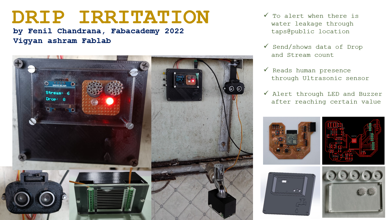
My final project slide,
My final project video,
Thanks to my local instructor, Suhas Labade, for helping me making the presentation slide in the last minute before the presentation.
Thanks to my colleague, Kishor Gaikwad, for helping me editing and compressing the presentation video in the last minute before the presentation.